

FC7000-UM-251-9370
8-2
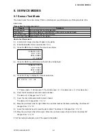
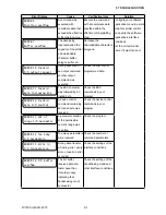
8. SERVICE MODES
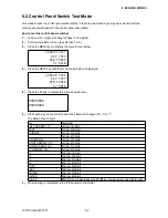
8.2 Control Panel Switch Test Mode
This mode checks the control panel switch status. If there is a bad switch you may have trouble with the
control panel switch panel or the control panel relay board.
How to test the control panel switches
(1) Load an A2 or larger size sheet of paper in the plotter.
(2) Enter the adjustment menu (see Section 7.3.6).
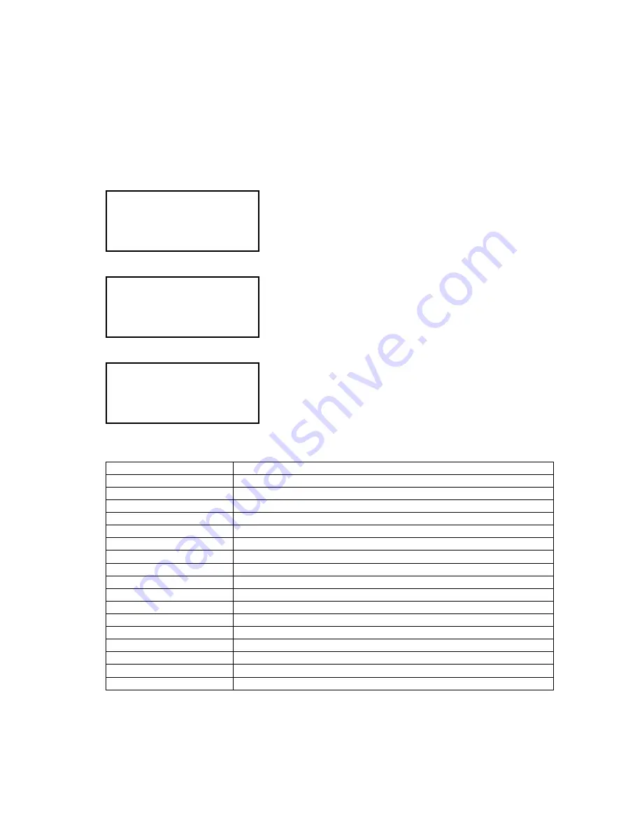
(3) Press the MENU key to display the menu shown below.
SENSOR TEST
KEY TEST
PEN FORCE
XY GAIN
(4) Press the NEXT key until the menu shown below is displayed.
SENSOR TEST
KEY TEST
PEN FORCE
XY GAIN
(5) Press the F2 key to display the menu shown below.
00000000
00000000
(6) Press each key on the control panel; the status will change from “0” to “1”.
The status of each digit:
Key
Status Bit
LEFT ARROW (-Y)
1st row 1st digit
NEXT
1st row 2nd digit
AXIS/RM
1st row 3rd digit
1st row 4th digit
CONDITION
1st row 5th digit
RIGHT ARROW (+Y)
1st row 6th digit
DOWN ARROW (-X)
1st row 7th digit
UP ARROW (+X)
1st row 8th digit
F1
2nd row 1st digit
F2
2nd row 2nd digit
F3
2nd row 3rd digit
F4
2nd row 4th digit
COPY
2nd row 5th digit
TEST
2nd row 6th digit
ORIGIN
2nd row 7th digit
ENTER
2nd row 8th digit
PAUSE
STATUS Lamp (lights when the PAUSE key is pressed, but only the first time)
(7) When testing is completed, turn off the power to the plotter.
Содержание FC7000-100
Страница 1: ...CUTTING PLOTTER SERVICE MANUAL FC7000 75 100 130 160 FC7000MK2 60 75 100 130 160 FC7000 UM 251 10 9370...
Страница 2: ......
Страница 8: ......
Страница 34: ......
Страница 38: ......
Страница 100: ......
Страница 110: ......
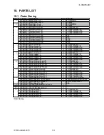
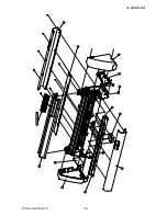
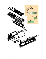
Страница 112: ...FC7000 UM 251 9370 10 2 10 PARTS LIST 1 2 3 4 5 6 7 8 10 9 Control Panel Assy 11 12...
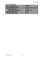
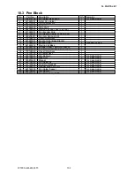
Страница 114: ...FC7000 UM 251 9370 10 4 10 PARTS LIST Control Panel 5 4 3 6 9 8 7 1 1 2 3 5 10...
Страница 126: ......
Страница 141: ...FC7000 UM 251 9370 11 15 11 BLOCK DIAGRAMS AND CIRCUIT DIAGRAMS 11 3 2 Main Board CPU...
Страница 142: ...FC7000 UM 251 9370 11 16 11 BLOCK DIAGRAMS AND CIRCUIT DIAGRAMS 11 3 3 Main Board FPGA...
Страница 143: ...FC7000 UM 251 9370 11 17 11 BLOCK DIAGRAMS AND CIRCUIT DIAGRAMS 11 3 4 Main Board I F...
Страница 144: ...FC7000 UM 251 9370 11 18 11 BLOCK DIAGRAMS AND CIRCUIT DIAGRAMS 11 3 5 Main Board Motor Drive...
Страница 145: ...FC7000 UM 251 9370 11 19 11 BLOCK DIAGRAMS AND CIRCUIT DIAGRAMS 11 3 6 Main Board Memory...
Страница 146: ...FC7000 UM 251 9370 11 20 11 BLOCK DIAGRAMS AND CIRCUIT DIAGRAMS 11 3 7 Main Board Power Supply...


