FC7000-UM-251-9370
3-8
3. OPERATIONS
3.4 Setting the Background Settings
SETTING PROCEDURE
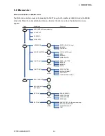
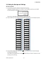
(1) Use the following procedure to display the background setting menus.
Load media in the plotter, and then turn on the power. Press the MENU key and then press the NEXT
key until the following menu appears.
PEN UP/DOWN>
BACKGROUND SETTINGS>
OPTION 1>
OPTION 2>
Press the F2 key (BACKGROUND SETTINGS) to enter the setting mode.
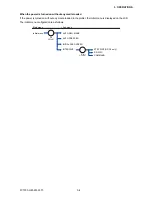
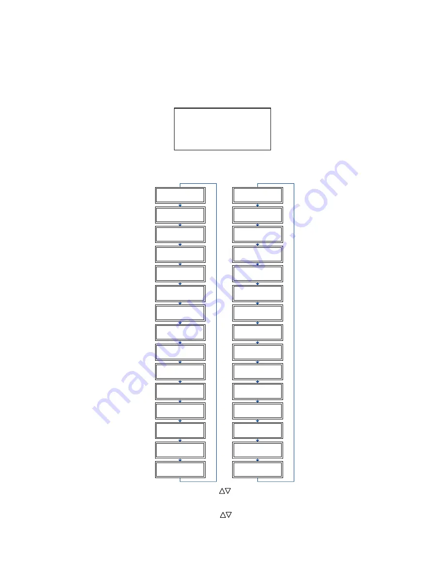
(2) Press the NEXT key to move through the BACKGROUND SETTINGS menus in the displayed sequence.
GP-GL
Background Settings
*2-Pen Model
*2-Pen Model
*2-Pen Model
*2-Pen Model
LANGUAGE SELECTION
[ JAPANESE ]
COMMAND ; AND :
ENABLED *
DISABLED
"W" COMMAND
PEN UP
PEN DOWN*
CONDITION PRIORITY
MANUAL*
PROGRAM
INITIAL BLADE
CONTROL POSITION
2mm BELOW *
OUTSIDE
LENGTH UNIT
INCH
METRIC*
PEN UP MOVE
ENABLED *
DISABLED
MEDIA SENSOR
ENABLED *
DISABLED
PINCH ROLLER SENSOR
ENABLED *
DISABLED
CROSS CUT PRESSURE
30
CHECK PEN
ENABLED *
DISABLED
FAN POWER
WEAK
NORMAL*
BEEP
FOR KEY OPERATION
OFF
ON*
MARK AUTO SCAN
ON
OFF *
LANGUAGE SELECTION
[ JAPANESE ]
MODEL EMULATED
7550*
7586
CONDITION PRIORITY
MANUAL*
PROGRAM
PEN SELECT
ENABLED*
DISABLED
PEN SELECT
ENABLED
DISABLED
INITIAL BLADE
CONTROL POSITION
2mm BELOW*
OUTSIDE
LENGTH UNIT
INCH
METRIC *
PEN UP MOVE
ENABLED
DISABLED*
MEDIA SENSOR
ENABLED*
DISABLED
PINCH ROLLER SENSOR
ENABLED*
DISABLED
CIRCLE RESOLUTION
AUTO
DEFAULT*
CROSS CUT PRESSURE
30
CHECK PEN
ENABLED *
DISABLED
FAN POWER
WEAK
NORMAL*
BEEP
FOR KEY OPERATION
OFF
ON*
MARK AUTO SCAN
ON
OFF*
HP-GL
TM
Background Settings
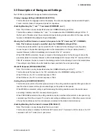
(3) At the LANGUAGE SELECTION menu, use the (
) POSITION keys to select the desired language
and then press the ENTER key.
At the CROSS CUT PRESSURE menu, use the (
) POSITION keys to increase or decrease the value
and then press the ENTER key.
Содержание FC7000-100
Страница 1: ...CUTTING PLOTTER SERVICE MANUAL FC7000 75 100 130 160 FC7000MK2 60 75 100 130 160 FC7000 UM 251 10 9370...
Страница 2: ......
Страница 8: ......
Страница 34: ......
Страница 38: ......
Страница 100: ......
Страница 110: ......
Страница 112: ...FC7000 UM 251 9370 10 2 10 PARTS LIST 1 2 3 4 5 6 7 8 10 9 Control Panel Assy 11 12...
Страница 114: ...FC7000 UM 251 9370 10 4 10 PARTS LIST Control Panel 5 4 3 6 9 8 7 1 1 2 3 5 10...
Страница 126: ......
Страница 141: ...FC7000 UM 251 9370 11 15 11 BLOCK DIAGRAMS AND CIRCUIT DIAGRAMS 11 3 2 Main Board CPU...
Страница 142: ...FC7000 UM 251 9370 11 16 11 BLOCK DIAGRAMS AND CIRCUIT DIAGRAMS 11 3 3 Main Board FPGA...
Страница 143: ...FC7000 UM 251 9370 11 17 11 BLOCK DIAGRAMS AND CIRCUIT DIAGRAMS 11 3 4 Main Board I F...
Страница 144: ...FC7000 UM 251 9370 11 18 11 BLOCK DIAGRAMS AND CIRCUIT DIAGRAMS 11 3 5 Main Board Motor Drive...
Страница 145: ...FC7000 UM 251 9370 11 19 11 BLOCK DIAGRAMS AND CIRCUIT DIAGRAMS 11 3 6 Main Board Memory...
Страница 146: ...FC7000 UM 251 9370 11 20 11 BLOCK DIAGRAMS AND CIRCUIT DIAGRAMS 11 3 7 Main Board Power Supply...

