
FC7000-UM-251-9370
7-19
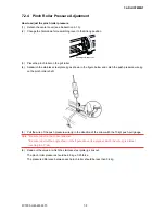
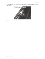
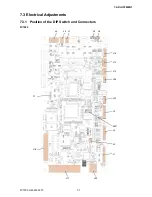
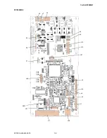
7. ADJUSTMENT
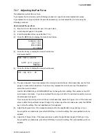
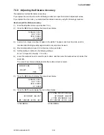
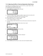
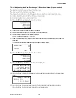
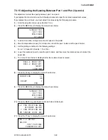
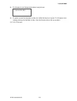
(9) Press the F2 key to start the test. The plotter immediately plots the test pattern, and the following menu
appears.
DADJ.X= 0 Y= 0
+X
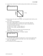
Y=300 mm
X=300 mm
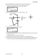
(10) Remove the paper and measure the Y-axis distance. If you have replaced the main board only, use the
recorded values.
(11) Input the values using the POSITION keys.
Press the LEFT or RIGHT ARROW key to select the Y-axis or X-axis distance adjustment.
The UP and DOWN ARROW keys are used to change the Y-axis or X-axis adjustment value.
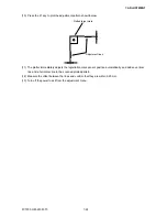
The formula of the input value is as follows:
Input value for X-axis = (300mm - measured X distance) x 10
Input value for Y-axis = (300mm - measured Y distance) x 10
For example:
If you measured 299.0mm for the Y-axis then input 10 for the adjustment value.
Adjustable range: -9.9 mm to +9.9mm , 0.1-mm steps
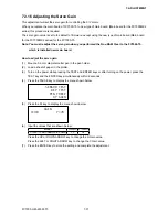
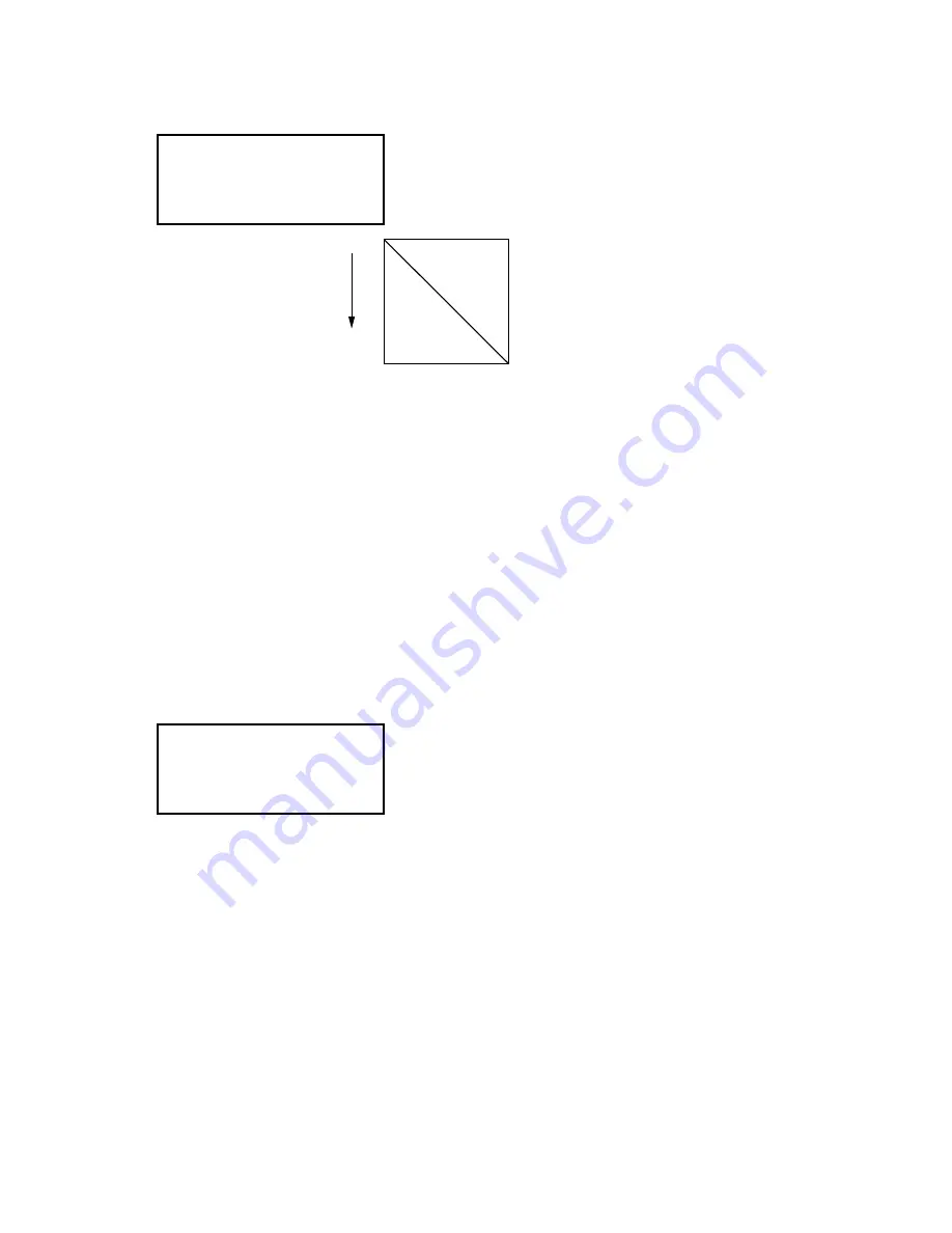
(12) Press the ENTER key to store the setting. The following menu appears.
XY LENG L=XXX.XX
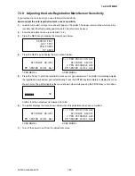
The value of the XY LENG L is showing the calculated value, so you do not need to adjust this value.
(13) If you wish to complete this adjustment, press the NEXT key. If you wish to plot the adjusted test
pattern, press the ENTER key.
(14) Turn off the power to exit from the adjustment menu.
Содержание FC7000-100
Страница 1: ...CUTTING PLOTTER SERVICE MANUAL FC7000 75 100 130 160 FC7000MK2 60 75 100 130 160 FC7000 UM 251 10 9370...
Страница 2: ......
Страница 8: ......
Страница 34: ......
Страница 38: ......
Страница 100: ......
Страница 110: ......
Страница 112: ...FC7000 UM 251 9370 10 2 10 PARTS LIST 1 2 3 4 5 6 7 8 10 9 Control Panel Assy 11 12...
Страница 114: ...FC7000 UM 251 9370 10 4 10 PARTS LIST Control Panel 5 4 3 6 9 8 7 1 1 2 3 5 10...
Страница 126: ......
Страница 141: ...FC7000 UM 251 9370 11 15 11 BLOCK DIAGRAMS AND CIRCUIT DIAGRAMS 11 3 2 Main Board CPU...
Страница 142: ...FC7000 UM 251 9370 11 16 11 BLOCK DIAGRAMS AND CIRCUIT DIAGRAMS 11 3 3 Main Board FPGA...
Страница 143: ...FC7000 UM 251 9370 11 17 11 BLOCK DIAGRAMS AND CIRCUIT DIAGRAMS 11 3 4 Main Board I F...
Страница 144: ...FC7000 UM 251 9370 11 18 11 BLOCK DIAGRAMS AND CIRCUIT DIAGRAMS 11 3 5 Main Board Motor Drive...
Страница 145: ...FC7000 UM 251 9370 11 19 11 BLOCK DIAGRAMS AND CIRCUIT DIAGRAMS 11 3 6 Main Board Memory...
Страница 146: ...FC7000 UM 251 9370 11 20 11 BLOCK DIAGRAMS AND CIRCUIT DIAGRAMS 11 3 7 Main Board Power Supply...


