


FC7000-UM-251-9370
6-3
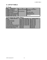
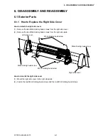
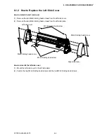
6. DISASSEMBLY AND REASSEMBLY
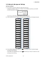
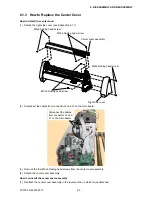
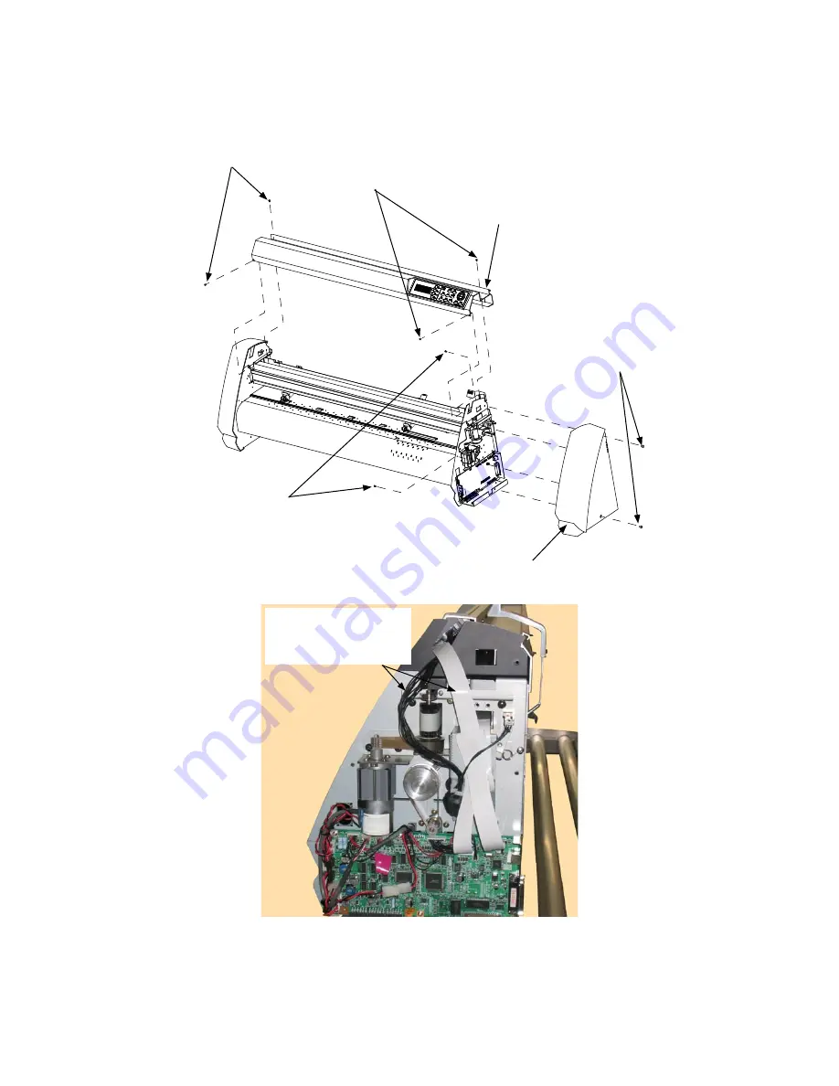
6.1.3 How to Replace the Center Cover
How to detach the center cover
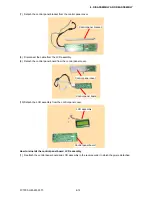
(1) Detach the right side cover (see Subsection 6.1.1).
M4L6 binding head screw
M3L6 binding head screw
M3L6 binding head screw
Right side cover
Center cover assembly
M3L6 binding head screw
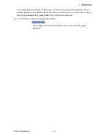
(2) Disconnect the cables from connector J2 and J3 on the main board.
Disconnect the cables
from connector J2 and
J3 on the main board.
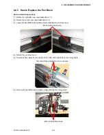
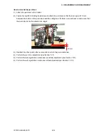
(3) Remove the four M3L6 binding head screws from the center cover assembly.
(4) Detach the center cover assembly.
How to reinstall the center cover assembly
(1) Reattach the center cover assembly in the reverse order in which it was detached.
Содержание FC7000-100
Страница 1: ...CUTTING PLOTTER SERVICE MANUAL FC7000 75 100 130 160 FC7000MK2 60 75 100 130 160 FC7000 UM 251 10 9370...
Страница 2: ......
Страница 8: ......
Страница 34: ......
Страница 38: ......
Страница 100: ......
Страница 110: ......
Страница 112: ...FC7000 UM 251 9370 10 2 10 PARTS LIST 1 2 3 4 5 6 7 8 10 9 Control Panel Assy 11 12...
Страница 114: ...FC7000 UM 251 9370 10 4 10 PARTS LIST Control Panel 5 4 3 6 9 8 7 1 1 2 3 5 10...
Страница 126: ......
Страница 141: ...FC7000 UM 251 9370 11 15 11 BLOCK DIAGRAMS AND CIRCUIT DIAGRAMS 11 3 2 Main Board CPU...
Страница 142: ...FC7000 UM 251 9370 11 16 11 BLOCK DIAGRAMS AND CIRCUIT DIAGRAMS 11 3 3 Main Board FPGA...
Страница 143: ...FC7000 UM 251 9370 11 17 11 BLOCK DIAGRAMS AND CIRCUIT DIAGRAMS 11 3 4 Main Board I F...
Страница 144: ...FC7000 UM 251 9370 11 18 11 BLOCK DIAGRAMS AND CIRCUIT DIAGRAMS 11 3 5 Main Board Motor Drive...
Страница 145: ...FC7000 UM 251 9370 11 19 11 BLOCK DIAGRAMS AND CIRCUIT DIAGRAMS 11 3 6 Main Board Memory...
Страница 146: ...FC7000 UM 251 9370 11 20 11 BLOCK DIAGRAMS AND CIRCUIT DIAGRAMS 11 3 7 Main Board Power Supply...


