FC7000-UM-251-9370
III
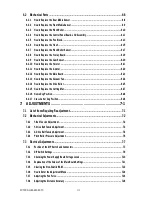
6.2 Mechanical Parts ......................................................................................................6-8
6.2.1 How to Replace the Rear Media Sensor .....................................................................................6-8
6.2.2 How to Replace the Front Media Sensor ....................................................................................6-9
6.2.3 How to Replace the Pinch Roller ............................................................................................. 6-10
6.2.4 How to Replace the Control Panel Board, LCD Assembly ......................................................... 6-11
6.2.5 How to Replace the Pen Block ................................................................................................ 6-13
6.2.6 How to Replace the Y-belt .......................................................................................................6-15
6.2.7 How to Replace the Pinch Roller Sensor .................................................................................. 6-17
6.2.8 How to Replace the Y-relay Board ...........................................................................................6-19
6.2.9 How to Replace the Cam Sensor .............................................................................................6-20
6.2.10 How to Replace the Y-motor ...................................................................................................6-21
6.2.11 How to Replace the X-motor ...................................................................................................6-22
6.2.12 How to Replace the Main Board ..............................................................................................6-23
6.2.13 How to Replace the Vacuum Fan .............................................................................................6-24
6.2.14 How to Replace the Drive Roller ..............................................................................................6-25
6.2.15 How to Replace the Cutting Mat ..............................................................................................6-27
6.2.16 Home Dog Position .................................................................................................................6-28
6.2.17 Cross Cutter Dog Position .......................................................................................................6-28
7. ADJUSTMENTS ..................................................................7-1
7.1 List of Items Requiring Readjustment ......................................................................... 7-1
7.2 Mechanical Adjustments ............................................................................................7-2
7.2.1 Y-Belt Tension Adjustment ........................................................................................................ 7-2
7.2.2 Y-Drive Belt Tension Adjustment ...............................................................................................7-3
7.2.3 X-Drive Belt Tension Adjustment ...............................................................................................7-4
7.2.4 Pinch Roller Pressure Adjustment .............................................................................................7-5
7.3 Electrical Adjustments ............................................................................................... 7-7
7.3.1 Position of the DIP Switch and Connectors ................................................................................ 7-7
7.3.2 DIP Switch Settings ..................................................................................................................7-9
7.3.3 Checking the Power Supply Board Voltage Levels .................................................................... 7-10
7.3.4 Explanation of the Values of the Main Board Settings .............................................................. 7-11
7.3.5 Clearing the Non-Volatile RAM ................................................................................................ 7-12
7.3.6 How to Enter the Adjustment Menu ......................................................................................... 7-14
7.3.7 Adjusting the Pen Force .......................................................................................................... 7-16
7.3.8 Adjusting the Distance Accuracy ............................................................................................ 7-18
Содержание FC7000-100
Страница 1: ...CUTTING PLOTTER SERVICE MANUAL FC7000 75 100 130 160 FC7000MK2 60 75 100 130 160 FC7000 UM 251 10 9370...
Страница 2: ......
Страница 8: ......
Страница 34: ......
Страница 38: ......
Страница 100: ......
Страница 110: ......
Страница 112: ...FC7000 UM 251 9370 10 2 10 PARTS LIST 1 2 3 4 5 6 7 8 10 9 Control Panel Assy 11 12...
Страница 114: ...FC7000 UM 251 9370 10 4 10 PARTS LIST Control Panel 5 4 3 6 9 8 7 1 1 2 3 5 10...
Страница 126: ......
Страница 141: ...FC7000 UM 251 9370 11 15 11 BLOCK DIAGRAMS AND CIRCUIT DIAGRAMS 11 3 2 Main Board CPU...
Страница 142: ...FC7000 UM 251 9370 11 16 11 BLOCK DIAGRAMS AND CIRCUIT DIAGRAMS 11 3 3 Main Board FPGA...
Страница 143: ...FC7000 UM 251 9370 11 17 11 BLOCK DIAGRAMS AND CIRCUIT DIAGRAMS 11 3 4 Main Board I F...
Страница 144: ...FC7000 UM 251 9370 11 18 11 BLOCK DIAGRAMS AND CIRCUIT DIAGRAMS 11 3 5 Main Board Motor Drive...
Страница 145: ...FC7000 UM 251 9370 11 19 11 BLOCK DIAGRAMS AND CIRCUIT DIAGRAMS 11 3 6 Main Board Memory...
Страница 146: ...FC7000 UM 251 9370 11 20 11 BLOCK DIAGRAMS AND CIRCUIT DIAGRAMS 11 3 7 Main Board Power Supply...


