4-21
Chapter 4 REGISTRATION MARK SETTINGS AND DETECTION
4.12 Registration Mark Detection
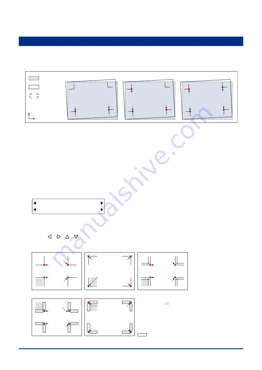
When MARKS has been selected for the regstraton mark mode, the plotter detects the regstraton marks
prnted on the medum and adjusts the angle of the coordnate axes (X-axs and Y-axs tlt) and the dstance
(lne segment length). Detecton of the regstraton marks can be performed ether automatcally or manually.
•
2-point reading
•
3-point reading
•
4-point reading
Point 2
Point 1
Point 2
Point 3
Point 1
Point 2
Point 3
Point 1
Point 4
Y
X
Registration marks
Plotter’s effective
plotting area
Edges of
the medium
2-point reading
: The plotter reads two regstraton marks n the X-axs drecton (ponts 1-2) and corrects the tlt n the
X-axs.
3-point reading
: The plotter reads the ponts at the rght angles of three regstraton marks (ponts 1-2 and ponts 1-3),
corrects the tlt n both coordnate axes and then performs dstance adjustment.
4-point reading
: The plotter reads the ponts at the rght angles of three regstraton marks (ponts 1-2 and ponts 1-3),
corrects the tlt n both coordnate axes and then performs dstance adjustment. The addton of the
coordnate values of pont 4 enables even more precse axal tlt correcton and dstance adjustment.
(1) Select MARKS as the regstraton mark mode, and then select the number of ponts for readng. (See Secton 4.2,
"Settng the Regstraton Mark Mode".)
(2) Wth the plotter n Ready status, press the
[ORIGIN] key
to dsplay the menu shown below.
FORCE
OFFSET
SPEED
QUALITY
1 3
2 MANUAL
The numbers 1, 2, and 3 dsplayed on ths menu are the MARK MOVE No. settngs. (See Secton 4.2, "Settng the
Regstraton Mark Mode".)
(3) Use the
[ ] [ ] [ ] [ ]
keys
to move the pen carrage (the tp of the tool selected by the current settng) to the
pont 1 area.
Registration mark pattern 1
Registration mark pattern 2
Registration mark pattern 3
Point 2
Point 3
Point 1
Point 1
Point 4
Point 2
Registration mark pattern Mirror 1
Point 1
Point 2
Point 3
Point 4
Registration mark pattern Mirror 2
Point 1
Point 3
Point 4
: Cutout area
Point 2
Point 2
Point 3
Point 1
Point 3
Point 4
Point 4
Move the tip of the tool selected by the
current setting within area.
Содержание FC2250 Series
Страница 1: ...USER S MANUAL MANUAL NO FC2250 UM 151 FC2250 SERIES CUTTING PRO...
Страница 105: ...5 29 Chapter 5 FUNCTION SETTINGS AND OPERATIONS Cutting Plotting Conditions List...
Страница 111: ...CHAPTER 6 TROUBLESHOOTING PRODUCT SUMMARY 6 1 Troubleshooting 6 2 Error Messages...
Страница 117: ...CHAPTER 7 VACUUM SUCTION PRODUCT SUMMARY 7 1 Selecting the Vacuum Pump 7 2 Installation Location 7 3 Vacuum Pump Wiring...
Страница 121: ...CHAPTER 8 SPECIFICATIONS PRODUCT SUMMARY 8 1 Main Specifications 8 2 External Dimensions...
Страница 130: ......


