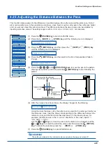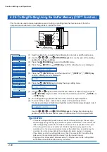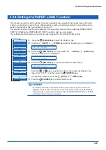
4-32
Function Settings and Operations
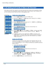
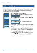
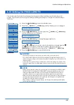
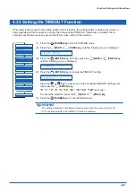
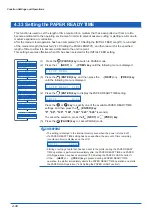
4.28 Setting the Format of Data to be Received
Before data is sent from the computer, the format (command mode) of data sent by the application software
must be checked. The cutting plotter accepts two data formats (command modes): GP-GL (Graphtec) and
HP-GL commands. Set the command mode to suit the application used.
Setting the Command Mode
(1) Press the
(PAUSE) key to switch to PAUSE mode.
(2) Press the
(NEXT) or
(PREV.) key until the following menu is displayed.
S E T U P M E N U
(3) Press the
(ENTER) key, and then press the
(NEXT) or
(PREV.) key
until the following menu is displayed.
C O M M A N D
(4) Press the
(ENTER) key to display the command-setting menu.
C O M M A N D G P - G L
(5) Press the
or
key to select "GP-GL" or "HP-GL," and then press the
(ENTER) key to confirm. To cancel the selection, press the
(NEXT) or
(PREV.) key.
(6) If "GP-GL" is selected, set the STEP SIZE. If "HP-GL" is selected, set the
ORIGIN POINT. If a command different from that set previously is selected, the
PAUSE mode is automatically canceled after STEP SIZE (GP-GL) or ORIGIN
POINT (HP-GL) is set.
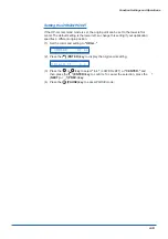
Setting the STEP SIZE
If the GP-GL command mode is set, the minimum unit of distance that the pen can
travel can be changed to one of four settings: 0.01 mm, 0.025 mm, 0.05 mm, or 0.1
mm. The default setting is 0.1 mm, so change this setting if your application specifies a
different step size.
(1) Set the command setting to "GP-GL."
C O M M A N D G P - G L
(2) Press the
(ENTER) key to display the step-size setting menu.
S T E P S I Z E 0 . 1 0 0 m m
(3) Press the
or
key to select "0.100 mm," "0.050 mm," "0.025 mm," or
"0.010 mm," and then press the
(ENTER) key to confirm. To cancel the
selection, press the
(NEXT) or
(PREV.) key.
(4) Press the
(PAUSE) key to cancel PAUSE mode.
B L A D E W A R E S E T U P
C U T L I N E P A T .
T A N G E N T I A L
I N I T . B
P E N U P S P E E D
I N I T I A L F E E D
T E S T
F E E D & C U T
P E N U P / D O W N
C L E A R B U F F E R
A U T O P R E F E E D
A D V A N C E D F U N C .
S E T U P M E N U
Содержание CE5000-120AP
Страница 1: ...CE5000 120AP USER S MANUAL MANUAL NO CE50AP UM 152 CUTTING PRO...
Страница 12: ...CHAPTER 1 Introduction 1 1 Checking the Accessories 1 2 Parts Names and Functions 1 3 Assembling the Stand...
Страница 103: ...A 4 Appendix Appendix C External Dimensions 1487 1020 1189 Units mm Dimensional accuracy 5 mm...

