


1-8
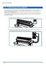
Introduction
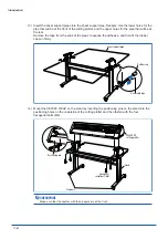
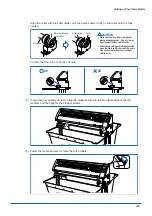
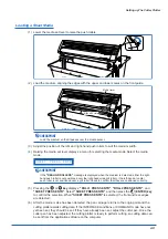
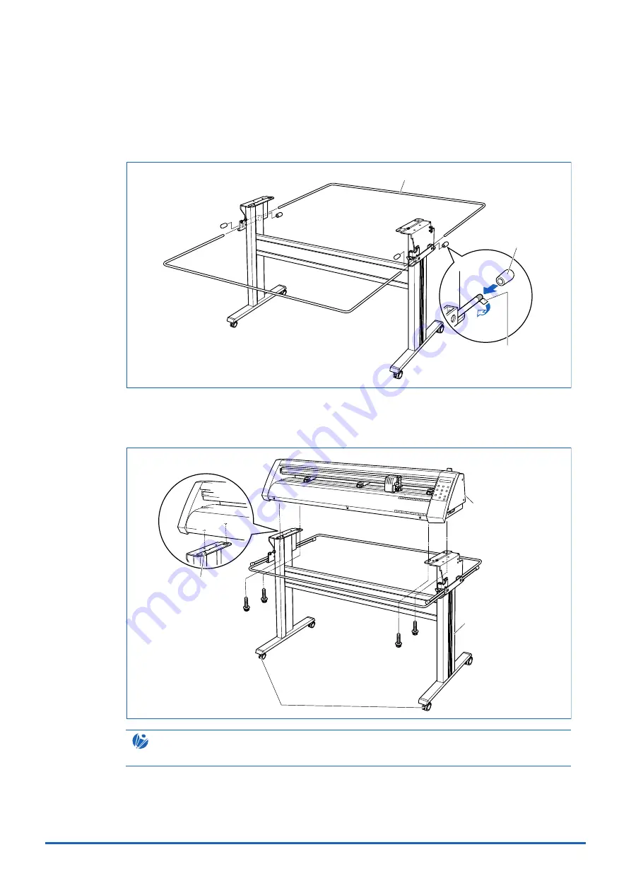
(3) Insert the sheet support pipes into the sheet support pipe brackets. Use the lower holes for the
pipe that will be at the front of the cutting plotter, and the upper holes for the pipe that will be at
the rear.
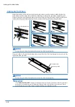
Remove the tape from the ends of the pipes to expose the adhesive, and then fit the rubber
caps on firmly.
Sheet support pipe
Rubber cap
Removable tape
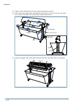
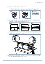
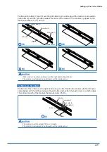
(4) Mount the CE3000-120AP on the stand by inserting the positioning pins on the stand into the
positioning holes on the underside of the cutting plotter and then fasten with the four
hexagonal bolts (M6).
Positioning pin
Hexagonal
socket bolt (M6)
Stand
CE5000AP
cutting plotter
Stoppers
CHECKPOINT
Make sure that the casters with the stoppers are at the front.
Содержание CE5000-120AP
Страница 1: ...CE5000 120AP USER S MANUAL MANUAL NO CE50AP UM 152 CUTTING PRO...
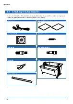
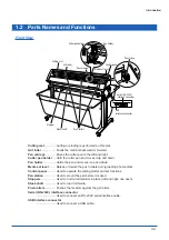
Страница 12: ...CHAPTER 1 Introduction 1 1 Checking the Accessories 1 2 Parts Names and Functions 1 3 Assembling the Stand...
Страница 103: ...A 4 Appendix Appendix C External Dimensions 1487 1020 1189 Units mm Dimensional accuracy 5 mm...


