background image

right or left, as required.

• 

Re-fit the three screws and 
washers. Tighten them down 
evenly to secure the pellet feed 
tube to the burner.

• 

Fit the pellet feed tube thermostat 
lead on to the thermostat 
terminals.

• 

Fit the pellet feed tube.

With the gasket correctly located, re-fit 
the burner to the combustion chamber 
door:
• 

Carefully insert the burner brazier 
through the opening and locate 
the holes in the burner flange onto 
the M8 studs (on either side of the 
burner).

• 

Secure the burner to the door 
with the two M8 nuts previously 
removed.

• 

Re-connect the plugs to their 
corresponding sockets on the left 
side of the burner.

• 

Ensure that each plug is fully 
pushed home until the small catch 
clicks into place. Refer to Figure 
4.8.

4.12 Pellet Hoppers

4.12.1 Single Boiler Installation

Position the pellet hopper on the same 
firm level surface as the boiler, on 
either the left-hand or right-hand side of 
the boiler (depending on hopper type 
used), with the top access door facing 
forwards. Refer to Figure 2-1 or 2-2 as 
required, for clearance dimensions and 
position.

36

Figure 4-8:

 Auger plug connection

4.12.2 Double boiler installation

Position the pellet hopper on the same 
firm level surface as, and in between, 
the two boilers, with the top access 
door facing forwards. Refer to Figure 
2-3 for clearance dimensions and 
position.
Failure to adhere to these 
measurements can cause blockage of 
the pellets in the pellet delivery hose 
or can prevent access for servicing at 
a later date. The hopper is supplied 
with castors which allows the hopper 
be moved during servicing. Once in 
the correct position, engage the brakes 
on the front castors to maintain this 
position.

4.13 Pellet Feed Auger

4.13.1 Single Boiler Hoppers

The pellet feed auger is supplied 
packed with the hopper but not factory-
fitted to it. 
To fit, unpack the hopper and auger. 
Remove the M5 screw fitted below 
the auger opening on the front of the 
hopper. Fit the end of the auger into 
opening in the front of the hopper as far 
as it will go and secure by fitting the M5 
screw through the auger fixing flange 
and tighten. See Figure 4-5.

4.13.2 Double Boiler Hoppers

Both augers on the ‘double boiler’ 
Intermediate hoppers are supplied 
factory-fitted to the hopper.
To connect the hopper to the boiler, 
fit one end of the pellet delivery hose 
onto the pellet feed auger outlet and 
the other end onto the pellet feed tube. 
The pellet delivery hose may need to 
be cut if too long. A sachet of lubricant 
is supplied in the accessories carton; 
apply the lubricant to the joint to ensure 
the pellet delivery hose is easily fitted. 
Ensure the pellet delivery hose is not 
kinked in any way.
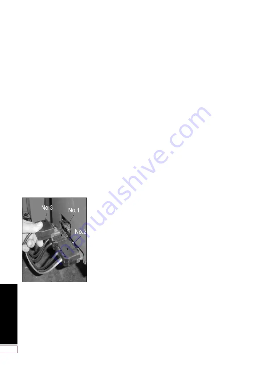
Fit the 6-way plug (No.3), from the 
pellet feed auger motor, into the 
corresponding 6-way socket on the left 
side of the burner. Ensure that the plug 
is fully pushed home until the small 
catch it clicks into place. See Figure 
4-6. Refer to Section 8.3 for all boiler 
plug connections.

4.14 Before you Commission

To avoid the danger of dirt and foreign 
matter entering the boiler the complete 
heating system should be thoroughly 
flushed out – both before the boiler is 
connected and then again after the 
system has been heated and is still hot.
This is especially important where 
the boiler is to be installed on an old 
system.
For optimum performance after 
installation, the boiler and the 
associated heating system must 
be flushed in accordance with the 
guidelines given in BS 7593:2006 
‘Treatment of water in domestic hot 
water central heating systems’. This 
must involve the use of a proprietary 
cleaner, such as Betz Dearborn’s 
Sentinel x300 or x400, or Fernox 
Restorer. Full instructions are supplied 
with the products but for more details 
visit either www.sentinel-solutions.net 
for Betz Dearborn products or www.
fernox.com for Fernox products.
After flushing the system, an inhibitor 
such as Sentinel X100 or Fernox MB-1 
should be used in accordance with the 
guidelines given in BS 7593:2006 for 
long term protection against corrosion 
and scale.

Grant Engineering (UK) Limited 
strongly recommends that a Grant 
Mag One in-line magnetic filter/s (or 
equivalent*) is fitted in the heating 
system pipework. This should be 
installed and regularly serviced 
in accordance with the filter 
manufacturer’s instructions.

* As measured by gauss. The Mag-
One magnetic filter has a gauss 
measurement of 12000.

4.15 Completion

Please ensure that the Grant Spira 
Commissioning form (supplied with the 
boiler) is completed in full and that it is 
signed by the householder/user.
Leave the white copy with the user, 
retain the pink copy for your own 
records, and return the yellow copy to 
Grant UK. Refer to Section 10-12.
Ensure that these Instructions are 
handed over to the householder.

Содержание Spira 5-18

Страница 1: ...UK DOC 0042 Rev 2 0 October 2015 Grant Spira 5 18kW 6 26kW and 9 36kW Condensing Wood Pellet Boiler User Installation and Servicing Instructions...

Страница 2: ...or appearances are changed in the interests of continued product improvement All good sold are subject to our official Conditions of Sale a copy of which may be obtained on application Grant Engineeri...

Страница 3: ...ils to Light 12 10 Emptying the Ash Pan 14 11 Cleaning and Servicing your Boiler 16 12 Ventilation 16 13 Electricity Supply 16 14 Sealed Central Heating system 16 15 Frost Protection 17 16 Corrosion a...

Страница 4: ...servicing The electrical connections to the boiler s are all made to the 4 way electrical plug on one of the three factory fitted flying leads at the rear of the pellet hopper All Grant pellet hopper...

Страница 5: ...r cylinder fitted as long as There are sufficient pellets of the correct type in the pellet hopper Refer to Section 3 The pellet auger is fully primed Refer to Section 7 The heating system controls ar...

Страница 6: ...resulting in clinker blocking air holes poor combustion and jamming of the brazier cleaning system DO NOT USE The auger will not be able deliver these pellets at the correct rate to the burner affecti...

Страница 7: ...at continually trips there may be a fault and you should contact your Installer CLEANING AUTO TEST switch When pressed and held in the TEST position it allows the installer or Grant service engineer t...

Страница 8: ...perate 5 C below the set point the boiler is in 100 power mode 5 C above the set point the boiler has reached minimum output The set point is NOT the temperature at which the burner stops The maximum...

Страница 9: ...essages The burner control panel display can also indicate that a fault has occurred with the boiler In the event of a fault one of the following error fault messages may be seen scrolling across the...

Страница 10: ...let feed auger on the pellet hopper MUST be fully primed BEFORE attempting to start the boiler The auger should be initially primed by the Installer as part of the commissioning process If for any rea...

Страница 11: ...and are calling for heat There should be a cursor next to the Heating Demand symbol on the burner display Refer to Section 5 4 Active Symbols Set the burner ON STANDBY switch to ON The flue fan will...

Страница 12: ...aller If after checking the above there is still a problem then contact your Installer for assistance STEP 2 Is one of the four ERROR MESSAGES scrolling across the bottom of the burner control panel d...

Страница 13: ...ocked with ash clinker If yes is the correct grade of pellets being used If not empty the hopper and refill with correct grade of pellet If after checking the above there is still a problem then conta...

Страница 14: ...procedure below Step 1 Set the burner STANDBY ON switch to STANDBY Step 2 If the boiler is running at the time wait for it to complete the burner shut down sequence i e until the burner control panel...

Страница 15: ...carefully lift the ash pan out of the boiler Refer to Figure 10 7 Do NOT use the centre cross bar of the ash pan as a carrying handle Step 10 Safely dispose of the ash WARNING Extreme care is require...

Страница 16: ...ly fails the boiler will cease to operate It should automatically relight when the electrical supply is restored However it may first burn off any smouldering pellets still present in the brazier befo...

Страница 17: ...t corrosion within your heating system and boiler your installer should have flushed the system and added a suitable corrosion inhibitor NOTE The Grant Guarantee on the boiler shell heat exchanger req...

Страница 18: ...heck Primary heat exchanger inspect clean Secondary heat exchanger inspect clean Wash system inspect clean Combustion chamber inspect clean Fan inspect clean Shaker mechanism grease Shaker system chec...

Страница 19: ...19 This page is intentionally left blank...

Страница 20: ...Requirements 52 8 2 Hopper Electrical 52 Connections 8 3 Boiler Hopper Plug 53 Connections 8 4 Heating System Controls 54 8 5 Connecting the Power 54 Supply 8 6 Wiring Diagrams 55 9 Burner 61 9 1 Bur...

Страница 21: ...e following special text formats are used in this manual for the purposes listed Warning of possible human injury as a consequence of not following the instructions in the warning Caution concerning l...

Страница 22: ...g pellets to the burner See Section 9 for details of burner operation The boiler is suitable for use on a sealed or open vented central heating system When commissioned and set correctly Grant Spira c...

Страница 23: ...pellet hopper available for use with a single boiler Left hand hopper to be positioned on the left hand side of the boiler Right hand hopper to be positioned on the right hand side of the boiler Both...

Страница 24: ...feed data 1 5 Boiler Cleaning and Servicing Grant Spira condensing wood pellet boilers are equipped with an automatic cleaning system for each of the two heat exchangers and also for the burner brazi...

Страница 25: ...t range C 55 to 75 C Boiler temperature cut out point C 65 to 80 C Minimum return temperature C 40 C Water system overheat cut out temperature C 100 C Burn back overheat thermostat cut out C 90 C Elec...

Страница 26: ...t 110kg pellet hopper full incl auger kg 151 151 151 Weight 200kg pellet hopper empty incl auger kg 77 77 77 Weight 200kg pellet hopper full incl auger kg 277 277 277 Weight of auger kg 8 8 8 Weight 1...

Страница 27: ...1120 6 26 200kg left hand hopper 1256 618 713 125 44 713 1160 1120 9 36 110kg left hand hopper 1056 518 513 277 196 661 1260 1220 9 36 200kg left hand hopper 1256 618 713 225 144 713 1260 1220 If the...

Страница 28: ...ht hand hopper 1256 618 713 125 44 713 1160 1120 9 36 110kg right hand hopper 1056 518 513 277 196 661 1260 1220 9 36 200kg right hand hopper 1256 618 713 225 144 713 1260 1220 If the measurement from...

Страница 29: ...Plan view 280 1232 280 A C 213 G 150 400 B B D E F 134 Spira wood pellet boiler model Dimensions A B C D E F G H 11 44 5 18 and 6 26 with double hopper 1792 616 697 224 141 616 1160 1120 12 52 2 x 6 2...

Страница 30: ...cts the calorific value of the pellet Low moisture content guarantees constant and predictable combustion efficiency Higher moisture contents can result in pellet breakdown Net Calorific Value This is...

Страница 31: ...ted between the bulk hopper and the boiler as the auger fitted to the hopper delivers the precise quantity of pellets required by the burner The pellet hopper also allows any problems with bulk pellet...

Страница 32: ...a longer auger can damage the pellets Grant UK offer a range of eight bulk pellet augers from 2 5m to 6m in length in 0 5m steps as given in the following table To determine the length of auger requi...

Страница 33: ...s which you must check with the local authority for the area e g Approved Document J Model and local Water Undertaking Bylaws MCS Installer Standards i e MIS 3004 if applying for the Renewable Heat In...

Страница 34: ...ose supplied already fitted within the boiler casing Connect one end of the hose to the outlet of the solenoid valve and the other to the inlet connection of the wash system manifold Connect the mains...

Страница 35: ...ber door Remove the red burner cover by loosening the four M5 screws two on each side of the cover and lifting it off the burner Disconnect the plugs from the left side of the burner Loosen the four s...

Страница 36: ...e boiler fit one end of the pellet delivery hose onto the pellet feed auger outlet and the other end onto the pellet feed tube The pellet delivery hose may need to be cut if too long A sachet of lubri...

Страница 37: ...ible and the number of bends kept to a minimum Pipes should be adequately fixed to prevent sagging i e at no more than 0 5 metre intervals Condensate disposal pipes must be fitted with a fall away fro...

Страница 38: ...blocking or frozen If connecting the condensate discharge into a waste system or soil stack either internally or externally a second trap must be fitted in the condensate discharge pipe This trap must...

Страница 39: ...r is set to operate at 2 5bar It should be fitted in the flow pipework near to the boiler The pipework between the safety valve and boiler must be unrestricted i e no valves The safety valve should be...

Страница 40: ...e 0 2 0 3 bar greater than the vessel charge pressure giving typical system fill pressures of approx 0 5 bar for a bungalow and 1 0 bar for a two storey house Refer to the Domestic Heating Design Guid...

Страница 41: ...s support options available in the Grant Biomass flue system Refer to Section 7 4 5 The minimum distance between the outer surface of any part of the flue system and any combustible material is 60mm R...

Страница 42: ...ce and a at least 1000mm above the highest point of intersection of the chimney and the weather surface or b at least as high as the ridge C Below on a pitched roof or within 2300mm horizontally to an...

Страница 43: ...the pellet hopper but not to the front or rear When fitting the Inspection Pipe to the fan box check the lip seal is fitted to the inner flue liner of the flue connector and the locking band is fitted...

Страница 44: ...m beyond the last support of the roof e g Roof Support Band a Guy Wire Bracket MUST be used and at every 1 5m thereafter Grant does not supply the guy wires or tie rods to use with this bracket Struct...

Страница 45: ...Plate product code WPB FP A Ventilated Fire Stop Plate should be fixed to the ceiling below a Ventilated Support Plate When passing through a second upstairs floor in a 3 storey house either a second...

Страница 46: ...Smoke Test I 7 6 Flue Notice Plate The Building Regulations Approved Document J requires a notice plate that conveys essential information regarding the flue installed to be permanently displayed A s...

Страница 47: ...45 bend Cantilever Wall bracket Rain cap Rain cap Rain cap Uni flashing Uni flashing Support plate 1000mm extension Ventilated firestop plate Support plate Ventilated firestop plate Extension Inspecti...

Страница 48: ...ominal length mm Effective length mm WPB EXT200 200 160 WPB EXT333 333 293 WPB EXT500 500 460 WPB EXT1000 1000 960 Adjustable 75 250mm Effective lengths using a straight and adjustable extension Produ...

Страница 49: ...40 300 WPB IP Inspection pipe WPB CA Flue adaptor WPB AP Anchor plate WPB FP Firestop plate 1 piece Support plate 2 pieces WPB GB Guy wire bracket WPB WB60 Wall bracket 60mm WPB CANT Cantilever 570mm...

Страница 50: ...cap WPB RS Roof support stainless steel band WPB SC Storm collar WPB TP Intermediate top plate WPB TC Trim collar for Wall Sleeve 45 454 259 184 330 1 0 0 0 300 WP SLE Wall sleeve 45 Also requires WP...

Страница 51: ...stable extension Extension 45 bend Support plate Adjustable extension Inspection pipe access hatch to face left of boiler 6 8 10 metre liner Anchor plate flex adaptor Flue system to flex adaptor Rain...

Страница 52: ...stallation This hopper is fitted with four pre wired flying leads with factory fitted plugs 4 way plug for connection of the permanent live earth and neutral and also the switched live from the heatin...

Страница 53: ...e 6 way plug to the corresponding connection on the flying lead from either the Grant SpiraVac system or Grant bulk pellet store auger Ensure that the plug and socket are fully pushed together until t...

Страница 54: ...ensure that the electrical supply is isolated at the fused spur serving the controls and boiler that the fuse has been removed and the isolator is locked off Do NOT connect the electrical supply to th...

Страница 55: ...BOILER WHEN VIEWED FROM THE FRONT Flue Fan Solenoid Valve Pellet Feed Auger Motor Plug No 3 6 way Plug No 1 7 way Plug No 2 7 way Plug No 4 5 way Plug No 5 5 way On On Switch Momentary one side Earth...

Страница 56: ...56 Figure 8 6 Burner wiring diagram SOCKET NO 1 SOCKET NO 2 SOCKET NO 3 21 A1 22 24 12 14 11 A2 9 10 11 12 13 15 14 16 17 18 19 20 22 23 24 21 L N 3 4 5 6 7 8 CN16 CN14 CN1...

Страница 57: ...PERMANENT LIVE SWITCHED LIVE To Low Pellet Warning Lamp ONLY USE IN HOPPER ONLY MODE IN LINE FUSE HOLDER C W 5 AMP FUSE 5 X 20mm IN LINE FUSE HOLDER C W 5 AMP FUSE 5 X 20mm Green Yellow Blue Black Br...

Страница 58: ...TCHED LIVE PERMANENT LIVE SWITCHED LIVE Supply to Central Heating Valve To Low Pellet Warning Lamp ONLY USE IN HOPPER ONLY MODE IN LINE FUSE HOLDER C W 5 AMP FUSE 5 X 20mm IN LINE FUSE HOLDER C W 5 AM...

Страница 59: ...t 1 C 2 E N L L N E 5A Fuse PL N SL L1 N L2 Four way plug comes fitted to four way socket on rear of Grant Spira Hopper N Grant 2 Channel Wall Mounted Programmer ESKIT L 1 2 3 4 OFF OFF ON ON HW HT HW...

Страница 60: ...Blue Green Yellow 1 C 2 White 13k 2W 270k 0 25W Room Stat 2 1 3 Link Figure 8 10 Heating system controls Y plan type system connection diagram Figure 8 11 Connection of Grant low water pressure switch...

Страница 61: ...ner restarts after maximum temperature has been reached WAIT PRELOAD BRAZIER operation code 40 Initial loading of pellets into the brazier to enable combustion to start Activated with a switched live...

Страница 62: ...duced T 120 Sec Lighting Feed Reduced 13 Pellet Burner Firing Max Flame Temp below the set point Temp Delta Range Flash Cleaning 1 Auger run time Time Clean Braz and or Time Clean Boiler Temp below th...

Страница 63: ...Normal Mode Increase temperature set point by 1 C up to 75 C maximum Menu mode Scroll up Button No 1 Button No 6 Button No 5 Button No 4 Button No 3 Button No 2 Normal mode Decrease temperature set p...

Страница 64: ...AL SETUP H2o POWER PELLET CLEAN ITALIAN ENGLISH TO RE LOAD FACTORY SETTING MEnu MANUFACT INSTAL 1 MEnu MANUFACT INSTAL 2 MEnu VIEW MANUFACT 3 MEnu USER VIEW 4 MEnu PSW 0 INSTAL TO STEP BACK 2 3 6 5 4...

Страница 65: ...adjustment during the installation commissioning of the appliance Only accessible with an access code The INSTAL folder has four sub folders menu 1 4 H2o menu 2 4 POWER PELLET menu 3 4 CLEAN menu 4 4...

Страница 66: ...LEAN BOILER has elapsed Default setting 5 18 6 26 and 9 36 60 60 seconds FLASH CLEANING Setting determines when the burner brazier and boiler cleaning operations start after the TIME CLEAN BRAZ and TI...

Страница 67: ...ressure Error 33 Failed Pellet Lighting 34 Servo Motor Blocked 40 Pre load 41 Wait Lighting Ignition 42 Wait Lighting Lighting Feed Reduced 45 Wait Lighting Flame Stabilisation 47 Probe Fault c VIEW C...

Страница 68: ...solenoid valve head is correctly fitted and secured in position with the steel clip provided with the boiler The solenoid valve is connected to an uninterrupted mains water supply Refer to Section 4 9...

Страница 69: ...ST does NOT operate the burner cleaning function but only that of the two heat exchangers Primary Heat Exchanger Check the shaker unit located in the top of the primary heat exchanger is operating fre...

Страница 70: ...ning process and recorded on the Commissioning Report form Refer to Section 10 12 With the electrical power to the hopper and boiler Switched on and the burner ON STANDBY switch set to STANDBY check t...

Страница 71: ...mber A draught reading of between 0 1 and 0 15mbar is required 0 04 and 0 06 in wg 10 9 2 Draught Stabiliser Adjustment The combustion chamber draught should be between of 0 1 to 0 15mbar 0 04 and 0 0...

Страница 72: ...w minutes to see the maximum and minimum values reached The CO2 measured should range between a maximum of 12 and a minimum of 10 If necessary the CO2 may have to be adjusted to be within these limits...

Страница 73: ...etc Combustion readings Installation details Burner settings Customer handover details The completed form must be signed by both installer and customer user A copy of the completed form must be left...

Страница 74: ...down and WAIT BOILER THERMOSTAT is shown on the burner control panel display before proceeding further Isolate the electrical supply to the hopper and boiler and remove the fuse from the fused spur Di...

Страница 75: ...panel cover and secure with the six screws previously removed Figure 11 6 Boiler control panel cover removed Figure 11 7 Cross section of shaker motor cam location covers omitted for clarity Figure 11...

Страница 76: ...from base of rear flue gas duct Clean and check condition of all spiral baffles Replace if necessary Re fit spiral baffles into heat exchanger tubes such that all the top edges of the baffles are run...

Страница 77: ...e 3 sided grate enclosure Remove the four M6 screws from inside the brazier and remove the grate enclosure Unscrew and remove the two M6 screws and washers one each side of the brazier chassis securin...

Страница 78: ...l out of the tube Do NOT pull on the element power cable Unscrew and remove the single screw securing the ignition element tube and pull it out of the burner Check the condition and thoroughly clean t...

Страница 79: ...leaks or blockages Clean or replace as necessary Check any other traps in the condensate disposal pipework Dismantle and thoroughly clean to remove any deposits Re fit to condensate disposal system p...

Страница 80: ...to Section 9 7 for details of how to access and check these settings Reset the SERVICE timer as follows Go to the CLEAN sub menu in the installer INSTAL menu Go to the RESET SERVICE setting Press butt...

Страница 81: ...se refer to Error Messages below It is essential at this stage to check and identify which of these three displays is shown on the burner control panel screen before proceeding to attempt to diagnose...

Страница 82: ...with the SpiraVac system Rectify as necessary When used with a Grant SpiraVac refer to instructions supplied with unit Note 4 Is there a switched live from the heating system controls connected to th...

Страница 83: ...Once the door catch is disengaged all power to the burner is interrupted Refer to Section 10 5 2 Check that catch is FULLY engaged when door is closed Note 6 Is the door microswitch operational Check...

Страница 84: ...84 Figure 12 6 Location of fuse on PCB Note 7 Is the fuse on the PCB OK Remove fuse from holder on PCB and check Replace if necessary Fuse type F5AL250V Refer to Figure 12 6...

Страница 85: ...capillary in good condition and not damaged kinked or broken Press reset Is there now continuity between the overheat stat terminals Is the system circulating pump operational Is there any restriction...

Страница 86: ...the overheat thermostat capillary for any damage replace if necessary Note 3 Is there continuity between the overheat thermostat terminals With electrical supply isolated reset the overheat thermosta...

Страница 87: ...s the duration of the boiler cleaning period correctly set Replace pellet delivery hose Correctly fit pellet delivery hose or replace if necessary Clean out the ash pan and boiler Clean all ash from t...

Страница 88: ...Empty and clean ash pan as necessary Is the flue system incorrectly installed or blocked Rectify as necessary Is the flue fan operational Is the room ventilation adequate If all the above are OK then...

Страница 89: ...of dust Is the correct grade of pellets being used Check power to element Check is element OK In burner menu reset TIME CLEAN BRAZIER TIME CLEAN BOILER settings Contact GRANT for advise to reset pell...

Страница 90: ...pull the complete element and cable from the tube Check the condition of the ceramic element and that it is correctly fitted into the ceramic socket Also check it is correctly positioned inside the t...

Страница 91: ...mbustion chamber door Yes No H2o 60 C SET 75 C SERVO MO Note 1 Opening the combustion chamber door Before attempting to open the combustion chamber door set the ON STANDBY switch to STANDBY Note 2 Can...

Страница 92: ...re held in place with the retaining clip supplied Note 3 Is thermistor connected to burner PCB With electrical supply to boiler still isolated remove both the burner cover and PCB cover Check the ther...

Страница 93: ...e burner fan operational Is the fan blocked Is air pressure switch operational Is the burner fan pressure correct Check plug connections between the burner fan and control PCB Remove any blockage or r...

Страница 94: ...any dust or debris If fan still does not rotate freely replace fan Note 3 Is the air pressure switch operational Check that air supply tube is correctly connected to the pressure switch and not block...

Страница 95: ...95 13 Spare Parts 13 1 Boiler Figure 13 1 Boiler components exploded view...

Страница 96: ...12 Air vent MPCBS29 1 1 1 13 Air fold manifold WPS48 1 1 1 14 22mm secondary to primary pipe WPS49 1 1 WPS50 1 15 Return assembly WPS51 1 1 WPS52 1 16 1 BSP flow pipe 5 18 and 6 26kW WPS53 1 1 1 BSP f...

Страница 97: ...S91 1 1 WPS92 1 43 Brass fitting 1 BSP x 22mm 311 WPS93 1 1 Brass fitting 1 BSP x 28mm 311 WPS94 1 44 Primary heat exchanger WPS95 1 1 WPS96 1 45 Combustion chamber baffle WPS97 1 1 WPS98 1 46 Ash pan...

Страница 98: ...Burner exploded view 1 6 3 4 20 13 27 28 21 31 19 22 32 23 5 14 15 18 33 2 7 8 26 9 24 12 11 10 17 16 25 36 kW only 29 30 36 kW 21 NOTE The 5 18kW model has an air adjuster disc not shown fitted bene...

Страница 99: ...74A 1 1 1 N A Pellet feed flexi tube WPS13 1 1 1 14 Pellet feed tube gasket WPS14 1 1 1 15 Burner fan gasket WPS24 1 1 1 16 Ignition element housing housing only WPS10B 1 1 1 17 Photocell tube WPS17 1...

Страница 100: ...100 Figure 13 4 200kg Pellet hopper components exploded view Figure 13 3 110kg Pellet hopper components exploded view 13 6 200kg Pellet Hopper Parts List 13 5 110kg Pellet Hopper...

Страница 101: ...ial 1 1 1 7 Grid Special 1 1 1 8 Top front panel Special 1 1 1 9 Door hinge WPS154 2 2 2 10 Top rear panel Special 1 1 1 11 Left side panel Special 1 1 1 12 Castor wheel WPS157 2 2 2 13 Rubber diaphra...

Страница 102: ...ible for implementing the Clean Air Act 1993 including designation and supervision of smoke control areas and you can contact them for details of Clean Air Act requirements The Grant Spira 5 18 6 26 9...

Страница 103: ...th skin and eyes After handling always follow normal good hygiene practices Protection Use disposable gloves face mask and eye protection First Aid Eyes if irritation occurs wash eyes with copious amo...

Страница 104: ...oblem is not being caused by the heating system or its controls Consult the installation and servicing instructions supplied with the boiler for guidance Ensure the problem is not being caused by poor...

Страница 105: ...ons even when the guarantee has expired to prolong the lifespan and ensure it is operating safely and efficiently 4 The guarantee period will commence from the date of installation unless the installa...

Страница 106: ...106 Notes...

Страница 107: ...107 This page is intentionally left blank...

Страница 108: ...GRANT ENGINEERING UK LTD Hopton House Hopton Industrial Estate Devizes Wiltshire SN10 2EU Telephone 44 0 1380 736920 Fax 44 0 1380 736991 Email info grantuk com Website www grantuk com...

Отзывы: