GMC-I Messtechnik GmbH
7
3
Operating Overview
3.1
Connections, Keys, Rotary Switch, Symbols
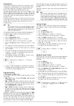
1 Charging status LED (charging mode – yellow: battery is charging, green:
fully charged)
for meanings of symbols
3 Softkeys (menu -dependent keys for selecting switching functions and
parameters, and for starting/ending measurements)
4
STORE:
Save key or push/print function for
IZYTRONIQ
5
OK:
Key for acknowledgment and for restarting the instrument from the
standby mode by pressing and holding
6
Rotary switch
for measuring functions, (see page 8 for meanings of symbols
7 DAkkS calibration seal
8 Connector sockets for current measurement with automatic blocking
earthing input
A current measurement input
9
S+/S–:
sense terminals for 4-wire measurements (m
/4)
10 Extended connection for Z270S probe
(operating instructions 3-349-996-15)
11 Connector sockets for voltage measurement with automatic blocking
earthing input
V,
, Temp
,
M
,
, ,
COIL measurement input
12
ESC:
Operating mode menu:
Press key briefly:
Exit the menu level – jump back to a higher level, exit
parameters entry without saving
Press and hold:
The instrument is switched to the standby mode. Switch
back on by pressing and holding the
OK
key.
13
MENU:
Key for accessing the five main menus.
14
Scroll keys:
Increase parameter values
Operating mode menu:
Selection of individual menu items
Decrease values
Operating mode menu:
Selection of individual menu items
Increase measuring range or move decimal point to right (
Man
function)
Decrease measuring range or move decimal point to left (
Man
function)
15 Brightness sensor
3.2
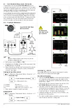
Symbols Used in the Digital Display
1 Momentary measuring function
2 Memory symbol
3
Important, in this case: Uext (interference voltage) or
warning regarding dangerous voltage: U > 15 V AC or U > 25 V DC
4 Battery charge level
5
Func:
switch back and forth amongst the functions of a given rotary
switch position
6
Data MinMax:
switch amongst “Data” (freeze measured value), “Min-Max
storage” and deactivate both functions
7
Man Auto:
switch back and forth between manual and automatic measur-
ing range selection
8 Display of the selected measuring range with manual measuring range
selection:
Select a lower measuring range
Select a higher measuring range
9 Selected test voltage
10 Select test voltage:
Select a larger test voltage
Select a smaller test voltage
11 Digital display with decimal point and polarity display
Measuring range exceeded:
OL
is displayed
12 Scale for analog display
13 Polarity selection
14
Zero:
Zero balancing active
15
Start/Stop:
For measurements which are not started automatically
16
Ip:
Test Current
2
3
4
1
5
6
8
13
Max. 1000 V!
12
15
14
11
7
9
10
Battery full
Battery OK
Battery weak
Battery (almost) dead, U < 3.3 V
Charge Levels
1
3
4
5
6
7
8
11
12
3
10
9
13
5
6
14
15
16
1%
REC
2
12
11
!


