22
GMC-I Messtechnik GmbH
6.3
Short-Circuited Coil Measurement – COIL Function
In combination with the optional
COIL TEST ADAPTER
, short-cir-
cuited coil measurements with a test voltage of 1000 V are possi-
ble within an inductance range of 10 μH to 50 mH at 100 Hz. This
range corresponds to motors in accordance with DIN standards
with power ratings of roughly 15 kVA to 80 MVA.
A semi-periodic time value which is proportional to the inductance
of the respective coil is ascertained during this measurement by
means of cyclical discharging with high-voltage for each motor
coil or coil combination, one after the other. A comparison of the
measurement results makes it possible to examine the motor
coils for symmetry, and thus to detect a short-circuited coil.
6.3.1
Preparing for Measurement
Note
Short-circuited coil measurements may only be con-
ducted on voltage-free coils.
➭
Set the rotary switch to “
RISO
” or “
COIL
”.
➭
Repeatedly press the
Func
softkey until the measurement view
for
COIL
appears at the display.
➭
Select the motor or coil type to be tested under the measure-
ment type parameter in “Setup for currently selected mea-
surement” (see below).
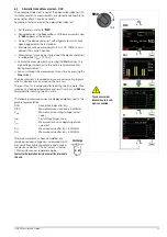
Selecting the Type of Measurement
> Momentary Measurement Setup > Parameter
Measurement Type
Coil / 1-Ph. Motor / 3-Ph. Motor
3 x > Measurement View
1-Ph. Motor:
AC motor (L1)
3-Ph. Motor:
3-phase motor (L1, L2, L3)
Coil
Motor with up to 15 coils (L1 - L15)
➭
Select polarity: unipolar or bipolar (see below).
Polarity Selection
> Momentary Measurement Setup > Parameter
Polarity
Bipolar / Unipolar
3 x > Measurement View
Test voltage (U
set
= 1000 V)
Test voltage for the short-circuited coil measurement is perma-
nently set to 1000 V and cannot be changed.
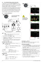
Connection and Contacting
➭
Connect the
COIL TEST ADAPTER
via the contact protected plug
of its connector cable to the two accessible sockets at the
multimeter: i.e. the red cable to the
COIL
socket and the black
cable to the
socket.
➭
Connect the two measurement cables to the sockets at the
COIL TEST ADAPTER
(identified with motor symbol).
➭
If possible, contact the inductive device under test with op-
tional alligator clips plugged onto the test probes. In the case
of 3-phase motors, for example, contact coil terminals U–V,
V–W and U–W or L1, L2 and L3, one after the other.
➭
Interference voltage measurement (V AC+DC TRMS) is con-
ducted in this switch position.
➭
The short-circuited coil measurement may only be started
when the device under test is voltage-free.
S–
A
V
Temp
m
/4
COIL
S+
0 V!
!
V
U
W
Example
COIL
COIL
TEST ADAPTER
with Star
M
Connect
COIL TEST ADAPTER and
measurement cables
UISO
1200 V!
> 500 A!
(pulse)
RISO
COIL
V
U
W
L1
L2
L3
Example
with Delta Connection
Connection
MENU
OK
OK
ESC
MENU
OK
OK
ESC
Func
Func
Func
Zero:
RISO
COIL
RISO
Coil
DAR
PI
The above symbol
blinks when test volt-
age is connected.
Func


