GMC-I Messtechnik GmbH
29
6.6.2
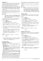
Duty Cycle Measurement – Duty AC
The pulse-period ratio can be ascertained for square-wave sig-
nals with the duty cycle measurement.
➭
Set the rotary switch to V~.
➭
Repeatedly press the
Func
softkey until
Duty AC
appears at the
display.
➭
Connect the measurement cables as you would for a voltage
measurement.
Make sure that a current measuring range (“A”) has not been acti-
vated, when the multimeter is connected for frequency or duty
cycle measurement!
The ratio of pulse duration to pulse period is measured with peri-
odic square-wave signals and is displayed as a percentage.
Note
The applied frequency must remain constant during duty
cycle measurement.
6.6.3
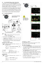
RPM Measurement – RPM AC
Revolutions per minute at 2 and 4-stroke internal combustion
engines (also known as rotational frequency) are measured by
acquiring pulses. The number of measurable pulses per revolution
varies depending upon engine type (2 or 4 stroke). As a prerequisite
for this measurement, the number of measurable pulses per revolution
must first be set in the RPM settings menu (RPM
0FF) (see
below).
➭
Set the rotary switch to V~.
➭
Repeatedly press the
Func
softkey until
RPM AC
appears at the
display.
➭
Select the desired motor
2-S
or
4-S
via the scroll keys
▲▼
.
➭
Connect the measurement cables as you would for a voltage
measurement. In the case of internal combustion engines, ig-
nition pulses can be acquired alternatively with a current sen-
sor (see wiring diagram).
➭
The measured value then appears in RPM, for example
“244.3 r”.
Measured RPM value
r
evolutions
p
er
m
inute
RPM parameter
p
ulses
p
er
r
evolution
Pulses per Revolution Settings Menu
2-S
RPM measurement at 2-stroke engines:
1 pulse per revolution) or
4-S
RPM measurement at 4-stroke engines:
1 pulse per 2 revolutions)
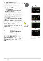
Voltage Comparator for Displaying Dangerous Voltage
The input signal or measuring signal is checked by a voltage com-
parator for dangerous spikes, because these do not appear at the
display when the low-pass filter is used.
At voltages of greater than 15 V AC or 25 V DC, a danger symbol
appears at the display:
Duty cycle (%) =
Pulse duration (t
E
)
Pulse period (t
P
)
100
RPM
Revolutions
min
---------------------------
Pulses
Revolution
-------------------------
x
60s
s
--------
=
S–
A
V
Temp
m
/4
COIL
S+
S–
A
V
Temp
m
/4
COIL
S+
Measuring ranges:
Max. 1000 V 3 kHz
Hz:
1 Hz
300 kHz
P
max
= 3 x 10
6
V x Hz
Duty AC:
2.0 ... 98.0%
RPM:
30 ... 30,000
V~
Hz
U
t
t
E
t
P
Pulse Time Quantities
f
P
pulse frequency = 1/t
P
t
E
pulse duration
t
P
pulse period
t
P
– t
E
interpulse period
t
E
/t
P
pulse or duty cycle
Duty AC measuring ranges:
MR
Hz
t
E
/t
P
3 V
15 Hz ... 1 kHz
2 ... 98%
1 kHz ... 4 kHz
10 ... 90%
30 V
15 Hz ... 1 kHz
5 ... 95%
1 kHz ... 4 kHz
10 ... 90%
M
Measuring ranges:
Max. 1000 V 3 kHz
Hz:
1 Hz
300 kHz
P
max
= 3 x 10
6
V x Hz
Func
Func
Func
VAC
Hz
Duty AC
RPM AC
VAC Fil
Func
Func
V
/~
I(A)
M


