background image

B l u e B o x   –   M e n u   O p e r a t i o n  


GO Systemelektronik GmbH  Faluner Weg 1    24109 Kiel     Germany  Tel.: +49 431 58080-0 

Fax: -58080-11 

Page 71 / 96 


www.go-sys.de    

                    [email protected]


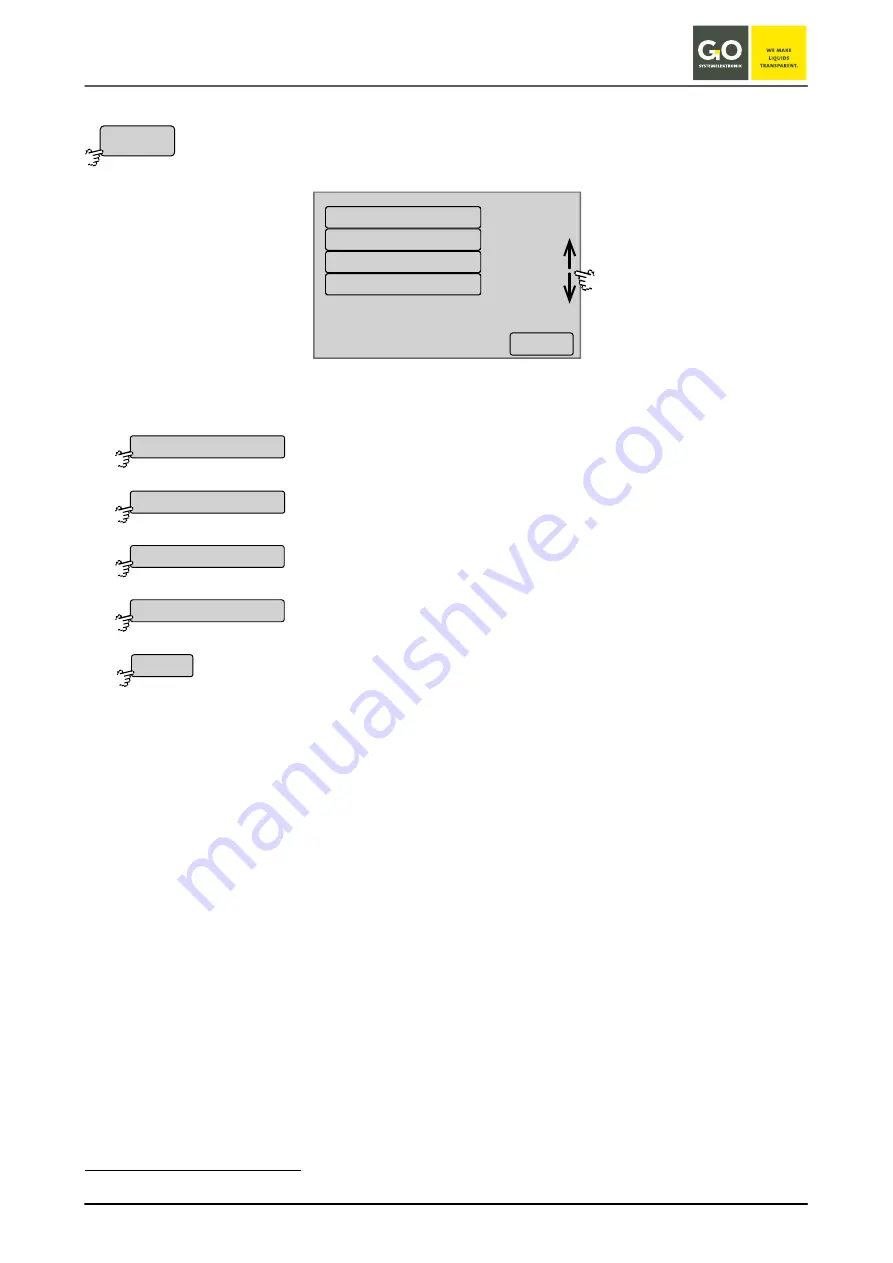
8.2.3 Actuator List 


Main menu 8.2 

Use this menu to access the menu of the connected actuators. 


The buttons of the actuators are arranged alphabetically

.  

In the example chosen here there are two relays and two current outputs. 


Switches to the menu of the first relay. 


Switches to the menu of the second relay. 


Switches to the menu of the first current output. see 

8.2.7 Current Output


Switches to the menu of the second current output. see 

8.2.7 Current Output


Switches back to the Main menu. 


  The sequence is that of the ASCII numeric value, i. e.: Special characters  

 numbers  

 capital letters  

 lower case letters 

Actuators

<–

1/1

Relay 1

bsa 845-A

bsa 845-A

Relay 2

Relay 1

Relay 2

bsa 503-A

bsa 503-B

<–

Scrolls the list. 

Содержание BlueBox T4

Страница 1: ...Manual BlueBox T4 Version of this manual 2 21 en www go sys de...

Страница 2: ...l identified dangers which could arise from the interaction between hardware and soft ware and from the use of other components Effective product observance is only possible with adequate information...

Страница 3: ...B l u e B o x GO Systemelektronik GmbH Faluner Weg 1 24109 Kiel Germany Tel 49 431 58080 0 Fax 58080 11 Page 3 96 www go sys de info go sys de blank page...

Страница 4: ...ower Supply 20 3 5 LAN Connection 21 3 6 Notes on the IP Protection Code 21 3 7 CAN bus Termination at the BlueBox 22 3 8 Jumper Position RS 232 RS 485 and RS 485 Termination at the BlueBox 22 4 Conne...

Страница 5: ...8 2 1 7 Language Settings 64 8 2 2 Sensor List 65 8 2 2 1 Sensor menus 66 8 2 2 1 1 Calibration 67 8 2 2 1 2 Table Display Sensor Values 68 8 2 2 1 3 Diagram Display Sensor Values 68 8 2 2 1 4 Sensor...

Страница 6: ...and the delivered product can result Please understand that no legal claims can be derived from the contents of this manual Comparison BlueBox T3 T4 Basic T4 Device BlueBox T3 BlueBox T4 Basic BlueBox...

Страница 7: ...ual interfaces for data processing and communication Due to its modular design the BlueBox system can handle almost all measurement and control functions More than 200 sensors and actuators can be con...

Страница 8: ...B l u e B o x GO Systemelektronik GmbH Faluner Weg 1 24109 Kiel Germany Tel 49 431 58080 0 Fax 58080 11 Page 8 96 www go sys de info go sys de System setup Network setup...

Страница 9: ...sensor power supply via the serial interface connection Interfaces 1x CAN 2x Relay output contact load 48 V 0 5 A 1x USB not TS and TC 1x Ethernet 10 or 100 Mbit s 1x RS 232 or RS 485 half duplex opt...

Страница 10: ...24 VDC 18 V 28 V 1 Power supply Switch on power 51 W Operation power max 15 W additionally up to 45 W for CAN bus modules powered by the BlueBox 2 Interfaces 1x CAN 1x USB 1x Ethernet 10 or 100 Mbit s...

Страница 11: ...d current output 2 are not galvanically isolated from each other therefore they must not be connected Otherwise falsified current values are generated 1 6 Notes on the Pulse Inputs The Blue Box T4 has...

Страница 12: ...a etc Configuration of the virtual sensors i e name unit interval etc as well as all AMS formulas Sensor values actuator values i e sensor measurement values actuator status values spectra calibration...

Страница 13: ...e that the labelled BlueBox operating voltage matches the supply voltage indicating the areas of power supply The correct functioning and operational safety of the device can only be ensured if the am...

Страница 14: ...e Box is used with an optional modem The Blue Box should be mounted on a vertical surface The drilling template is used for mounting on a flat surface Please choose suitable mounting screws and dowels...

Страница 15: ...ale RS 232 or RS 485 the selection is set with the associated jumpers2 optional with 4 pin M8 panel plug and 12 VDC power supply 7 Current output 1 connection via a 4 pin M8 panel socket female 4 to 2...

Страница 16: ...x T4 Power supply 24 VDC panel plug M12 male 3 24 VDC 4 GND 24 V CAN bus panel socket M12 female 1 CAN H 2 CAN L 3 24 VDC 4 GND 24 V Relay outputs panel socket M12 female 1 NC1 normally closed 1 2 NO1...

Страница 17: ...plug M8 male RS 232 1 GND GND RS 485 3 RX RX TX 4 TX RX TX RS 232 or RS 485 with optional power supply panel plug M8 male RS 232 1 GND GND RS 485 2 12 VDC 12 VDC 3 RX RX TX 4 TX RX TX Current output 4...

Страница 18: ...e USB port at the BlueBox is designed for data export and for firmware update1 5 L AN connection for LAN cables in standard or cross link design see also 3 5 LAN connection 6 Serial interface connecti...

Страница 19: ...r Pin Assignment at the BlueBox T4 Basic Power supply 24 VDC panel plug M12 male 3 24 VDC 4 GND 24 V CAN bus panel socket M12 female 1 CAN H 2 CAN L 3 24 VDC 4 GND 24 V RS 232 or RS 485 panel plug M8...

Страница 20: ...ox should only be installed by a qualified person using suitable tools Incorrect instal lation can result in serious malfunction and could damage the instrument Make sure that your power grid has suit...

Страница 21: ...nnecting to a network you need a standard RJ 45 cable For connecting to a PC you need a RJ 45 crosslink cable Only if the PC has no automatic switch of the network interface Please ensure that the RJ...

Страница 22: ...and set the respective termination switch to either On or Off 3 8 Jumper Position RS 232 RS 485 and RS 485 Termination at the BlueBox The serial interface of the BlueBox is factory preset to RS 232 u...

Страница 23: ...39 0001 the colour coding according to the table below applies 2 Connection with clamp sockets see 4 2 Note the correct terminal assignment in the module based on the circuit board labelling When usin...

Страница 24: ...arking is invalid Only the num bering of the contacts is valid 4 2 Connection with Spring Clips Note the correct terminal assignment in the module based on the circuit board labelling The CAN bus cabl...

Страница 25: ...ments at the end of the CAN bus chain final ele ments must have a terminating resistor of 120 each This prevents signal reflections and interference Elements within a CAN bus chain pass elements must...

Страница 26: ...y ele ment within the CAN bus system The easiest way to take the measurement is at the openings below the clamp sockets see next col umn Make sure that all elements of the CAN bus chain are voltage fr...

Страница 27: ...ndependent power supply Long cable lengths are not recommended for safety relevant applications The connection is made via clamp sockets on the board slots The termination of the single bus lines is c...

Страница 28: ...l Number A1234 BlueBox Password PIN xxxxx Storage Device SST 512 Serial Number Serial number of the BlueBox With this serial number the BlueBox is identified by the BlueBox PC Software set at the fact...

Страница 29: ...for a modem connection set at the factory not changeable Password Network password of the BlueBox Is needed to access the BlueBox via the AMS software set at the factory not changeable 3 BlueGate Sett...

Страница 30: ...s actuators and virtual sensors3 After 20 seconds or after pressing OK the Parameter display 8 1 appears The device tries to repair a faulty file system automatically If this does not work the service...

Страница 31: ...fo go sys de Password entry To access certain menus a password consisting of 5 digits must be entered The password can be found in the configuration data sheet Deletes the last entered digit Verifies...

Страница 32: ...nsors and actuators are displayed Selection via 8 2 2 1 Sensor menu and 8 2 4 1 Actuator menu All sensors and actuators are displayed All sensors are displayed The selection of the displayed sensors a...

Страница 33: ...f the previous sensor actuator Switches the cycling of the parameter display off Switches to the parameter display of the next sensor actuator Switches the cycling of the parameter display off Switche...

Страница 34: ...ay and the number of pages in this case 1 2 In the upper right corner time and date is displayed Buttons Switches to the parameter display of the previous sensor Switches the cycling of the Parameter...

Страница 35: ...play of the previous sensors actuators Switches the cycling of the parameter display off Switches to the display of the next sensors actuators Switches the cycling of the parameter display off Switche...

Страница 36: ...1 System menu Switches to the menu of the sensor list see 8 2 2 Sensor List Switches to the menu of the actuator list see 8 2 3 Actuator List Switches to the service menu see 8 2 4 Service Mode Switc...

Страница 37: ...to the Network menu see 8 2 1 1 Network menu Switches to the Time menu see 8 2 1 2 Time menu Shuts down the BlueBox see 8 2 1 3 Shutdown Switches to the Modem menu see 8 2 1 4 Modem menu Modem Setting...

Страница 38: ...etmask see 8 2 1 1 2 IP Netmask Input Switches to the input of the IP address of the device which executes the connection to other networks see 8 2 1 1 3 Gateway IP Address Input Default Gateway Switc...

Страница 39: ...layed Enter the IP address using the numeric buttons in the marked block 2 Network IP Address 192 168 1 167 Netmask 255 255 255 0 Gateway 0 0 0 0 Port 14111 Login Name bluebox Password xxxxx see 6 The...

Страница 40: ...etmask the netmask defines the IP address range of the network The netmask is configured at the factory see 6 The Configuration Data Sheet The current setting is displayed Input of the netmask with Bu...

Страница 41: ...he connection another BlueBox routers servers etc The current setting is displayed Enter the IP address using the numeric buttons in the marked block 2 Network IP Address 192 168 1 167 Netmask 255 255...

Страница 42: ...yed in GO Systemelektronik provides a time server under the URL ntp go sys IP address 212 51 30 18 the only requirement here is that the BlueBox has Internet access Saves the input and switches back t...

Страница 43: ...the menu of the Gateway settings of the Internet connection Switches to the menu of the DynDNS settings of the Internet connection Only by a connection via GPRS UMTS modem For service tasks GO System...

Страница 44: ...te View Encryption on View Encryption off Switches to the input of the IP address of the destination computer Switches the AES encryption of the connection off and on Default Encryption off The button...

Страница 45: ...displayed Enter the IP address using the numeric buttons in the marked block If an access to the BlueGate server has been ordered from GO Systemelektronik the IP address is set to the standard address...

Страница 46: ...gs 8 2 1 1 5 1 The current password is displayed in Saves the input and switches back to the UDP settings Deletes the last entered character Switches back to the UDP settings without saving the input...

Страница 47: ...nput of the password of the gateway Switches back to the Internet Settings menu Example BlueGate Gateway from GO Systemelektronik 3 BlueGate Settings IP Address 212 51 30 18 Gateway IP Password BlueGa...

Страница 48: ...0 0 0 Saves the entry and switches back to the Gateway Settings Internet menu 8 2 1 1 5 2 2 Input Gateway Password Internet Gateway Settings Internet 8 2 1 1 5 2 The current password is displayed in S...

Страница 49: ...er of the name under which the BlueBox can be reached via DynDNS Enter of the login name of your DynDNS account Enter of the login password of your DynDNS account Opens a selection list of Internet ad...

Страница 50: ...e current setting is displayed in Saves the input and switches back to the DynDNS Settings menu Deletes the last entered character Switches back to the DynDNS Settings without saving the input Host Na...

Страница 51: ...dresses for Internet addresses then a DNS server must be entered here in the BlueBox Switches back to the Network menu Enter the IP address using the numeric buttons in the marked block Selects the ne...

Страница 52: ...hes to the input of the date Switches to the input of the time Switches to the input of the time drift Switches to the input of the time zone Switches between winter and summer time The button is also...

Страница 53: ...election of month setting Selection of year setting Selection 1 Selection 1 Switches back to the Time menu 8 2 1 2 2 Time of the Day Input Time menu 8 2 1 2 Selection of hour setting Selection of minu...

Страница 54: ...clock runs faster negative values The BlueBox clock runs slower Deletes the last entered character Saves the input and switches back to the Time menu Switches back to the Time menu without saving the...

Страница 55: ...BlueBox before disconnecting the power supply Shutdown of the BlueBox Switches back to the System menu The shutdown status is displayed The shutdown is complete You can switch off the BlueBox by disc...

Страница 56: ...r of the modem Only visible if modem type GSM or GPRS UMTS is selected in the Modem type settings see 8 2 1 4 3 Modem Type Settings Is only visible if a SMS sending is possible Precondition SMS compat...

Страница 57: ...is activated for the modem by the manufacturer via this button Switches back to the Modem menu Modem Settings 8 2 1 4 2 Input of the Modem PIN number Modem menu 8 2 1 4 Note on a possible operation er...

Страница 58: ...used to enter the modem type of a connected modem The buttons are also status indicators No modem is connected A GSM modem is connected An ISDN modem is connected An Analogue modem is connected A GPR...

Страница 59: ...ord Switches the routing on and off The button is also a status indicator Factory default routing off Switches back to the Modem menu The routing must be switched on if you use this BlueBox as an Inte...

Страница 60: ...current setting is displayed in Saves the input and switches back to the UMTS Settings Deletes the last entered character Switches back to the UMTS Settings without saving the input APN Username Pass...

Страница 61: ...ed Display of dial in information Modem reset Switches back to the Modem menu 8 2 1 5 GPS Menu System menu 8 2 1 Switches to the settings of the connection of a GPS receiver Switches to a selection me...

Страница 62: ...PC 104 then this interface is activated by the manufacturer If a factory mounted GPS receiver is connected to the USB interface the USB interface for the GPS receiver is activated at the factory Only...

Страница 63: ...Parameter display 8 way1 Parameter display 6 way Parameter display single see 8 1 Parameter display The button is also a status indicator Defines which sensors actuators2 will be displayed in the mult...

Страница 64: ...indicator Selection menu language English the button is also a status indicator Selection menu language Spanish the button is also a status indicator Selection menu language French the button is also...

Страница 65: ...gue actuators and are calibrated similar to the sensors see also 8 2 7 Current Output The buttons are arranged in alphabetical order You can change the name of a sensor and a current output if require...

Страница 66: ...input of a sensor name max 20 characters Is queried by other BlueBox programs Switches to the input of the unit of the measurement value More than 5 characters cannot be displayed on the BlueBox displ...

Страница 67: ...calibration procedure is preset examples see Appendix B Calibrating of a pH Sensor or Appendix C Calibration of a Galvanic Oxygen Sensor If the calibration procedure is not pre set you can press the b...

Страница 68: ...t values over the last 21 24 hours depends on the measurement range scaled to min max of all measurement values Pressing the display switches back to the sensor menu Measurement values over the past 2...

Страница 69: ...l number 8 digit designation of the Data Acquisition Module consecutive number of the sensor 0 9 Interval Measurement interval of the sensor Average Measurement average Resolution Measurement resoluti...

Страница 70: ...horter the download time Averaging The measurement value is the arithmetic average of the selected number of single measurements Current settings are displayed as Actual value Deletes the last entered...

Страница 71: ...chosen here there are two relays and two current outputs Switches to the menu of the first relay Switches to the menu of the second relay Switches to the menu of the first current output see 8 2 7 Cu...

Страница 72: ...the actuator behaviour Switches to the info menu of the actuator Switches back to the Actuator list 8 2 3 1 1 Set Actuator menu Actuator menu 8 2 4 1 This menu allows you to determine the state of a...

Страница 73: ...tor ID CAN ID serial number 8 digit designation of the Data Acquisition Module consecutive number of the actuator 0 9 Interval Control interval for the actuator function request Average 1 Default valu...

Страница 74: ...l be a request whether the compressed air cleaning of the spectrome ter has to be deactivated in the service time After the expiry of the displayed time the service mode will be disabled The service m...

Страница 75: ...enu of the first variable The current value of the user variable is displayed Switches to the input menu of the first variable Switches back to the menu of the user variable Here you can change the va...

Страница 76: ...ystem Information Help menu 8 2 6 Number of connected sensors actuators and virtual sensors Serial number and Firmware version and Storage Firmware Version of the BlueBox Display whether an uninterrup...

Страница 77: ...mA Menu I Switches to the input of calibration values 2 Switches to the inpu of a calibration mode 2 see 8 2 2 1 1 Calibration Selects the current output for the multiple parameter display or not see...

Страница 78: ...arithmeti cal means gives the measurement value see 8 2 2 1 5 Switches to the input of the measurement resolution Input 1 corresponds to decimal place 0 in the Sensor setup of AMS2 Input 0 1 correspon...

Страница 79: ...While switching on power press display until the notice touch adjustment don t touch for normal use appears Left off the display immediately Press the display immediately again for more than one secon...

Страница 80: ...only operable if in the associated sensor setup window of the AMS software the entry in the parameter field begins with pHGlas 1 1 Calibration Menu pH Sensor 80 1 1 pH Sensor Calibration 81 1 2 pH Se...

Страница 81: ...the electrode in clean tap water At the right border of the last menu there is a quality factor graphically displayed Calculated from offset and slope If during the calibration procedure the permissib...

Страница 82: ...in pH 7 pH 0 mV Slope 59 16 mV pH unit Switches back to the Calibration menu pH sensor Switches back to the Calibration menu pH sensor 1 3 pH Sensor Offset Calibration Menu pH Sensor input offset valu...

Страница 83: ...1 Page 83 96 www go sys de info go sys de 1 4 pH Sensor Slope Calibration Menu pH Sensor Input minus value each 0 1 mV pH Input plus value each 0 1 mV pH Switches back to the Calibration menu pH senso...

Страница 84: ...til the displayed values are stable Start window of the calibration Further with mg l Cal Back with Input Oxygen content of the measuring medium according to the reference measuring instru ment here f...

Страница 85: ...ration menu will appear precondition is that the sensor generates a voltage of less than 3 mV Start window 0 mg l Further with 0 Offset Cal quit without saving Further with YES Back with NO Save save...

Страница 86: ...4112 UDP 212 51 30 18 For bidirectional communication with the BlueBox the following port must be configured Port 14003 TCP 212 51 30 18 For Windows Software communication the following port must be c...

Страница 87: ...a folder Database2 on the first level was previously plugged into the USB port of a BlueBox The BlueBox then automatically transfers all measurement data of the BlueBox into the Database folder 2 The...

Страница 88: ...Appendix F Opening of a BlueBox Housing Danger Shut down the BlueBox Disconnect the BlueBox from the power supply 1 Remove the covers on both sides of the BlueBox 2 Unscrew the four fixing screws 3 O...

Страница 89: ...erial number of a power supply is on the type plate on the right side of the housing This work must be carried out by qualified persons using suitable tools Check the input voltage level Overvoltage m...

Страница 90: ...80 11 Page 90 96 www go sys de info go sys de Position of the switch Colour of the switch red Position of the slide switch Slide switch to the right 230 VAC Slide switch to the left 110 VAC Push the s...

Страница 91: ...n e c t i o n s T 4 GO Systemelektronik GmbH Faluner Weg 1 24109 Kiel Germany Tel 49 431 58080 0 Fax 58080 11 Page 91 96 www go sys de info go sys de Appendix H Mainboard Connections BlueBox T4 BlueB...

Страница 92: ...x M a i n b o a r d C o n n e c t i o n s T 4 GO Systemelektronik GmbH Faluner Weg 1 24109 Kiel Germany Tel 49 431 58080 0 Fax 58080 11 Page 92 96 www go sys de info go sys de BlueBox serial number u...

Страница 93: ...i o n s T 4 B a s i c GO Systemelektronik GmbH Faluner Weg 1 24109 Kiel Germany Tel 49 431 58080 0 Fax 58080 11 Page 93 96 www go sys de info go sys de Appendix I Mainboard Connections BlueBox T4 Bas...

Страница 94: ...a i n b o a r d C o n n e c t i o n s T 4 B a s i c GO Systemelektronik GmbH Faluner Weg 1 24109 Kiel Germany Tel 49 431 58080 0 Fax 58080 11 Page 94 96 www go sys de info go sys de BlueBox serial num...

Страница 95: ...sensor minimal measurement value 51 Maximal measurement value overrun virtual sensor maximal measurement value 52 Internal communication error COM 53 Underrun of the lower limit of the AD converter AD...

Страница 96: ...c l a r a t i o n o f C o n f o r m i t y GO Systemelektronik GmbH Faluner Weg 1 24109 Kiel Germany Tel 49 431 58080 0 Fax 58080 11 Page 96 96 www go sys de info go sys de Appendix K EU Declaration of...

Отзывы: