


RP6 ROBOT SYSTEM - 2. Installation of the Expansion Module
Before you can mount the module on
the robot, you need to loosen the four
screws on the main board. Eventually
you can also carefully loosen the small
connector of the bumper PCB so that
you can completely lift up the main
board. However this is not necessary if
you manage to pass your fingers under
the main board in order to fasten the
spacer bolts with the M3 nuts.
Caution:
When you re-connect the
cable to the bumper PCB, you have to
pass one finger under the sensor PCB
to compensate the pressure to avoid
that the PCB is pushed too much back-
wards. Alternatively you can also unscrew the two screws on the bumper PCB and
leave the cable mounted.
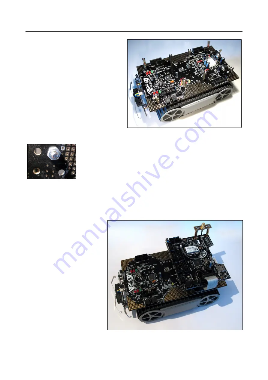
Then you can fasten the four 25mm M3 spacer bolts one after
the other with the M3 nuts in the mounting holes on the main
board as shown on the picture.
On the picture above, all 8 spacer bolts are fastened, also those
of a second expansion module!
After that, you put the expansion module on top of the spacer bolts and fasten it via
the four M3 screws. You can also proceed the other way round: start by screwing the
spacer bolt on the expansion module and fasten it afterwards with the nuts on the
main board.
Finally you have to plug in the 14-pin XBUS ribbon cable and that's it.
Unlike the other RP6 expansion
modules, there is NO USRBUS
connection because of a lack
of space on the PCB at that loc-
ation.
We recommend to mount the
RP6-M256 on the rear expan-
sion stack of the robot in the
top position to optimize the in-
stallation of the antenna and
the optional display. As a side
effect, both programming con-
nectors remain accessible on
the same side of the robot. On
the front edge you can mount
the experiment expansion
module RP6-EXP (see picture
on the following pages for a
configuration example).
- 14 -


