25
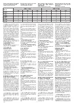
Modell
MCB - C Type
MCB - D Type
16A
20A
25A
16A
20A
25A
288LED
1
2
2
1
2
3
80LED
1
2
2
1
2
3
216LED
2
2
2
2
3
4
64LED
1
2
2
1
2
3
15 LED
2
2
2
2
3
4
20 LED
1
2
2
1
2
3
È consigliabile, per ogni proiettore, utilizzare
un interruttore bipolare da 16 Ampere con
caratteristiche di intervento di tipo C o D (è
preferibile il tipo MCB – D). Non superare il
numero massimo di apparecchi per interruttore
(vedere tabella sopra). Eventuali teleruttori
devono essere sovradimensionati e di tipo
gravoso. Eventuali differenziali devono essere
con I∆ ≥ 0,3÷0,5mA, ritardati di tipo S. Per
interruttori tripolari e quadripolari (è preferibile
il tipo MCB – D) moltiplicare per 3 il numero
di proiettori indicati in tabella; ovviamente i
proiettori devono essere distribuiti su tutte le
fasi in modo equilibrato. Per l’alimentazione di
potenza del proiettore vedere il:
• collegamento linea-proiettore
Per versione LEDMASTER ONE simmetrico con
cablaggio interno o con cablaggio esterno on
board (vedere
figura 23
).
•
collegamento linea-gruppo di
cablaggio-proiettore
Per versione LEDMASTER ONE simmetrico con
cablaggio separato (vedere
figura
24
).
USO E MANUTENZIONE
Manutenzione ordinaria
• Pulizia del vetro da eseguire una volta l’anno.
• Pulizia generale del proiettore da eseguire
una volta l’anno.
• Per piastre armadio: verificare spia dell’SPD
in corrente alternata all’ingresso della piastra e
sostituire se di luce rossa.
• Per piastre DMX: verificare anche la spia
dell’SPD sul cavo di segnale DMX e sostituire
se di luce rossa.
In caso di mancata prima accensione o di
mal funzionamento
In caso l’apparecchio installato non funzioni,
come prima cosa, accertarsi che arrivi
tensione all’apparecchio. In caso non vi siano
interruzioni di linea, accertarsi di aver eseguito
correttamente i collegamenti elettrici.
Pertanto ripetere minuziosamente il punto:
• Collegamento elettrico esecuzione CL. I;
a seconda della versione.
Non è ammessa nessuna modifica della
componentistica dell’apparecchio se non
precedentemente concordata con FAEL Luce.
Se l’apparecchio continua a non funzionare
contattare il produttore.
INDIVIDUAZIONE DEL DRIVER DA SOSTITUIRE
IN CASO DI MAL FUNZIONAMENTO
Qualsiasi tipo di manutenzione alla
componentistica può essere effettuata solo
da personale qualificato. Prima di accedere
all’interno dell’apparecchio o di eseguire
qualsiasi operazione di manutenzione,
accertarsi che sia disconnessa l’alimentazione
dell’apparecchio. Fare riferimento alla
figura
43
per individuare la porzione (1, 2, 3 o 4)
dell’apparecchio non funzionante. Il numero
della porzione non funzionante corrisponderà
al numero del driver non funzionante (D1,
D2, D3 o D4); fare riferimento alla
figura
44
per l’individuazione del driver da sostituire in
relazione alla tipologia di cablaggio utilizzata:
• vedere
figura 44a
per “apparecchio cablato
esternamente on board (versione SIMMETRICA;
versione con 4/3 drivers) – vers. 230V e vers.
400V”
• vedere
figura 44b
per “apparecchio con
gruppo di alimentazione separato con cassetta
di derivazione on board versione SIMMETRICA”
Piastra di alimentazione IP20
È it is recommended to use for each projector
a two-pole 16 amps switch with C or D type
tripping characteristics (preferably the MCB - D
type).
Do not exceed the maximum number of
appliances per switch (check the table above).
All contactors must be oversized and heavy-duty
type.
The differential circuit breakers must of the
delayed type, with ∆ ≥ 0.3÷0.5 mA.
For 3-pole and 4-pole switches (preferably of
the MCB - D type), multiply by 3 the number
of projectors indicated in table; obviously, the
projectors must be evenly distributed on all
phases.
For the power supply of the projector check:
•
the line-projector connection
Symmetrical version LEDMASTER ONE with
internal wiring or with built-in external wiring
(check the
figure 23
).
•
the line-wiring unit-projector connection
Symmetrical version LEDMASTER ONE with
separated wiring (check
figure 24
).
USE AND MAINTENANCE
Routine maintenance
• Clean the glass once a year.
• Perform the general cleaning of the projector
once a year.
• Cabinet plates: check the SPD indicator in
alternating current at the plate input and replace
if the light is red.
• DMX plates: check also the SPD indicator on
the DMX signal cable and replace if the light is
red.
In case of failed start up or fault
If the device installed is not working, first make
sure it is powered.
If there are no line breaks, ensure you
have successfully completed the electrical
connections.
Therefore repeat thoroughly the point:
• ELECTRICAL CONNECTION EXECUTION CL. I;
depending on the version.
Do not modify the components of the device
unless agreed upon with FAEL Luce.
If the appliance still does not work, contact the
manufacturer.
HOW TO INDENTIFY A DRIVER TO BE
REPLACED IN CASE OF FAULT
Any type of maintenance operation on the
components can only be performed by qualified
personnel.
Before accessing inside the appliance or
performing any maintenance operations, make
sure that the appliance is disconnected from the
power supply.
Refer to the
figure
43
to identify the faulty part
(1, 2, 3 or 4) of the projector.
The number of the faulty part matches the
number of the faulty driver (D1, D2, D3 or D4);
refer to
figure
44
for the identification of the
driver to be replaced depending on the cables
used:
• check the
figure 44a
for the “built-in
externally wired appliance (SYMMETRICAL
version; version with 4/3 drivers) - version 230V
and version 400V”
• check the
figure 44b
for “appliance with
separated power supply unit with built-in cables
box SYMMETRICAL version” IP20 power supply
plate
Numero massimo di apparecchi comandabili
da ciascun interruttore magnetotermico.
Soluzione valida per tutte le versioni:
Maximum number of projectors that can be
controlled by each circuit breaker.
This solution applies to all versions:
Nombre maximum d’appareils pouvant être
commandés depuis chaque interrupteur
magnétothermique.
Solution valable pour toutes les versions:
On conseille, pour chaque projecteur, d’utiliser
un interrupteur bipolaire de 16 Ampères avec
des caractéristiques d’intervention de type C
ou D (le type MCB – D est à préférer). Ne pas
dépasser le nombre maximum d’appareils
par interrupteur (voir tableau ci-dessus). Tout
éventuel télérupteur doit être surdimensionné et
de type lourd. Tout éventuel différentiel doit être
avec I∆ ≥ 0,3÷0,5mA, retardés de type S. Pour
interrupteurs tripolaires et quadripolaires (le
type MCB – D est préférable) multiplier par 3 le
nombre de projecteurs indiqués en tableau; les
projecteurs doivent être évidemment distribués
sur toutes les phases de façon équilibrée.
Pour l’alimentation de puissance du projecteur,
voir le:
•
branchement ligne-projecteur
Pour version LEDMASTER ONE symétrique avec
câblage interne ou avec câblage externe on
board (voir
figure 23
).
•
branchement ligne-groupe de
câblage-projecteur
Pour version LEDMASTER ONE symétrique avec
câblage séparé (voir
figure
24
).
UTILISATION ET ENTRETIEN
Entretien courant
• Nettoyage du verre à effectuer une fois par an.
• Nettoyage général du projecteur effectuer
une fois par an.
• Pour les plaques de l’armoire: vérifier le
témoin de l’SPD en courant alterné à l’entrée de
la plaque et remplacer si de lumière rouge.
• Pour plaques DMX: vérifier également le
témoin de l’SPD sur le câble de signal DMX et
remplacer si de lumière rouge.
Dans le cas de premier démarrage manqué
ou de mauvais fonctionnement
Si l’appareil à peine installé ne fonctionne pas,
s’assurer avant tout que la tension arrive à
l’appareil. S’il n’y a pas de coupure de courant,
assurez-vous d’avoir effectué correctement les
branchements électriques.
Par conséquent, répéter minutieusement le
point:
•
Branchement électrique exécution CL. I
;
selon la version.
Aucune modification des composants de
l’appareil n’est consentie si non concordée au
préalable avec FAEL Luce. Si l’appareil continue
à ne pas fonctionner, contacter le producteur.
IDENTIFICATION DU DRIVER À REMPLACER EN
CAS DE MAUVAIS FONCTIONNEMENT
La maintenance des composants ne peut
être effectuée que par du personnel qualifié.
Avant d’accéder à l’intérieur de l’appareil ou
d’effectuer toute opération de maintenance,
assurez-vous que l’alimentation de l’appareil
est bien déconnectée. Se référer à la
figure
43
pour identifier la portion (1, 2, 3 o 4) de l’appareil
non fonctionnant. Le numéro de la portion non
fonctionnant correspondra au numéro du driver
non fonctionnant (D1, D2, D3 o D4); se référer à
la
figure
44
pour identifier le driver à remplacer
selon le type de câblage utilisé:
• voir
figure
44a
pour “appareil câblé
extérieurement on board (version SYMÉTRIQUE;
version avec 4/3 drivers) - vers. 230V et vers.
400V”
• voir figure
44b
pour “appareil avec groupe
d’alimentation séparé avec boite de dérivation
on board version SYMÉTRIQUE” Plaque
d’alimentation IP20
Maximale Anzahl von Geräten, die von jedem
magnetothermischen Schalter gesteuert
werden können.
Lösung gültig für alle Versionen:
EEs wird empfohlen, für jeden Scheinwerfer
einen zweipoligen Schalter mit 16 Ampere mit
Eingriffseigenschaften vom Typ C oder D zu
verwenden (der Typ MCB - D ist vorzuziehen).
Die maximale Anzahl von Geräten pro Schalter
nicht überschreiten (siehe Tabelle oben). Alle
Fernschalter müssen überdimensioniert und
schwer sein. Alle Differentialschalter müssen
mit I∆ ≥ 0,3 ÷ 0,5mA, verzögerte Art S sein. Bei
dreipoligen und vierpoligen Leistungsschaltern
(Typ MCB-D ist vorzuziehen) die Anzahl der in
der Tabelle angegebenen Scheinwerfer mit 3
multiplizieren; die Scheinwerfer müssen natürlich
in allen Phasen ausgewogen verteilt sein. Zur
Stromversorgung des Scheinwerfers siehe:
• Anschluss Linie-Scheinwerfer
Für die symmetrische Version LEDMASTER
ONE mit interner Verkabelung oder externer
Verkabelung On-Board (siehe
Abbildung
23
).
•
Anschluss Linie-Verkabelungseinheit-
Scheinwerfer
Für die symmetrische Version LEDMASTER ONE
mit getrennter Verkabelung (siehe
Abbildung
24
).
BEDIENUNG UND WARTUNG
Gewöhnliche Wartung
• Reinigung des Glases einmal pro Jahr.
• Allgemeine Reinigung des Scheinwerfers
einmal pro Jahr.
• Für Schrankplatten: Prüfen Sie die
SPD-Kontrolllampe im Wechselstrom am
Platteneingang und ersetzen Sie sie, wenn sie rot
leuchtet.
• Für DMX-Platten: Überprüfen Sie auch die
SPD-Kontrolllampe am DMX-Signalkabel und
ersetzen Sie sie, wenn sie rot leuchtet.
Im Falle eines fehlgeschlagenen ersten
Einschaltens oder bei einer Betriebsstörung
Wenn das installierte Gerät nicht funktioniert,
stellen Sie zunächst sicher, dass das
Gerät eingeschaltet ist. Wenn keine
Leitungsunterbrechungen auftreten, vergewissern
Sie sich, dass Sie die elektrischen Anschlüsse
ordnungsgemäß hergestellt haben.
Dafür vorsichtig den folgenden Punkt wiederholen:
• Elektrischer Anschluss Ausführung Cl. I;
je nach Version.
Änderungen der Bauteile des Gerätes sind nicht
zugelassen, außer wenn zuvor mit FAEL Luce
vereinbart. Wenn das Gerät immer noch nicht
funktioniert, wenden Sie sich an den Hersteller.
IDENTIFIZIERUNG DES AUSZUTAUSCHENDEN
TREIBERS BEI BETRIEBSSTÖRUNG
Die Wartungsarbeiten an den Komponenten
dürfen nur von qualifiziertem Personal
durchgeführt werden. Bevor Sie auf das Innere
des Gerätes zugreifen oder Wartungsarbeiten
durchführen, stellen Sie sicher, dass das Gerät
von der Stromversorgung getrennt ist. Siehe
Abbildung 43
für die Identifizierung des nicht
funktionierenden Teils (1, 2, 3 oder 4) des
Gerätes. Die Nummer des nicht funktionierenden
Teils entspricht der Nummer des nicht
funktionierenden Treibers (D1, D2, D3 o D4);
siehe
Abbildung
44 für
die
Identifizierung des
auszutauschenden Treibers in Bezug auf die Art
der verwendeten Verkabelung:
• siehe
Abbildung
44a
für extern verkabelte On-
Board Geräte (SYMMETRISCHE Version; Version
mit 4/3 Treiber ) – Vers. 230V und Vers. 400V”
• siehe
Abbildung 44b
für “Gerät mit getrennter
Versorgungseinheit mit Verteilerkasten On-Board
SYMMETRISCHE Version” Versorgungsplatte IP20
28
Содержание 514084501
Страница 1: ...Glamox O92 O93 SYM User manual ...
Страница 6: ...3 3 6 ...
Страница 7: ...4 7 ...
Страница 11: ...8 11 ...
Страница 12: ...9 12 ...
Страница 15: ...12 15 ...
Страница 17: ...14 17 ...
Страница 20: ...17 20 ...
Страница 24: ...21 24 ...
Страница 26: ...23 26 ...
Страница 29: ...26 29 ...
Страница 30: ...27 30 ...
Страница 32: ...29 32 ...
Страница 33: ...30 33 ...
Страница 34: ...31 34 ...
Страница 35: ...35 ...
Страница 36: ...36 ...
Страница 37: ...34 37 ...
Страница 39: ...35 Note 39 ...


