8
DISPOSITIVI DI SICUREZZA
4
4
SAFETY DEVICES
The tyre changer has a number of safety devices designed to guar-
antee the utmost operator safety:
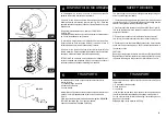
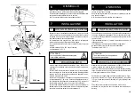
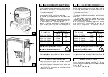
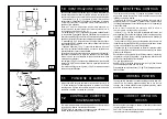
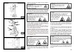
1. Check valve on the spindle opening hydraulic line (inside the swivel
connector, see fig. B/1). This prevents the wheel from falling from the
spindle if the hydraulic line is accidentally broken.
2. Pressure relief valve factory set at 130 bar ±10% (See Fig. B/2).
This limits the pressure in the hydraulic circuit and ensure correct
operation of the plant.
3. Pump motor overload cut-out (inside the electric enclosure).
This cuts in if the motor overheats to prevent it from burning out.
4. Check valve on the chuck arm lifting hydraulic line. It prevents the
chuck arm from descending when any accidental break occurs in
the hydraulic circuit.
CAUTION!
Removing or tampering with safeties is in violation of European Safety
Regulations and relieves manufacturer of any and all liability for injury
to persons to damage to things caused or referable to such acts.
Lo smontagomme è dotato di una serie di dispositivi preposti a
garantire la massima sicurezza per l'operatore :
1) Valvola di non ritorno sulla linea di apertura dell'autocentrante
(situata all'interno del raccordo girevole, vedi Fig. B/1). Evita una
possibile caduta della ruota dovuta ad accidentali rotture del circuito
oleodinamico.
2) Valvola di massima pressione - tarata a 130 Bar ±10%-
(vedi Fig. B/2).
Limita la massima pressione sul circuito oleodinamico salvaguardan-
do il buon funzionamento dell'impianto.
3) Interruttore magnetotermico di protezione del motore pompa
(situato all'interno della centralina elettrica). Interviene in caso di
surriscaldamento del motore evitandone la bruciatura.
4) Valvola di non ritorno sulla linea idraulica di sollevamento del
braccio mandrino. Evita una possibile discesa del braccio mandrino
dovuta ad accidentali rotture del circuito oleodinamico.
ATTENZIONE: La rimozione o manomissione dei dispositivi di si-
curezza comporta una violazione delle norme europee e solleva il
costruttore dai danni causati o riferibili agli atti suddetti.
TRASPORTO
5
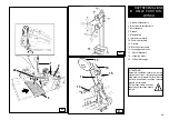
La macchina viene fornita, secondo richiesta del cliente in tre
diverse versioni:
1- in cassa di legno con pallet
2- fissata sul solo pallet
3- senza imballo
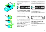
Nella prima e nella seconda versione deve essere movimentata per
mezzo di un fork-lift posizionando le lame nei punti indicati in
Fig. A/2.
Per le altre versioni seguire le indicazioni del paragrafo "MOVIMEN-
TAZIONE" riportate a pag. 58 di questo manuale.
Il peso della macchina imballata è di 850 Kg.
TRANSPORT
5
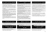
Depending on customer request, the machine is delivered in 3 pack-
ing versions:
1- in a wooden crate with pallet
2- fixed to a pallet
3- no packing
In the first and second case, the machine must be handled with a
fork-lift truck with the forks positioned as shown in the figure A/2.
For the other versions, follow the “Handling” instructions given on
page 58 of this manual.
Shipping weight for the machine is 850 kg.
KG. 850
B/2
B/1
A/2
Содержание S 551 XL A
Страница 64: ...64 SCHEMA ELETTRICO ELECTRIC DIAGRAM SCHEMA ELECTRIQUE SCHALTPLAN ESQUEMA ELECTRICO 1 110 V 1 ph...
Страница 65: ...65 230 V 1 ph...
Страница 66: ...66 220 V 3 ph...
Страница 67: ...67 400 V 3 ph...
Страница 68: ...68 SCHEMA ELETTRICO ELECTRIC DIAGRAM SCHEMA ELECTRIQUE SCHALTPLAN ESQUEMA ELECTRICO 2...
Страница 72: ......


