34
N
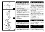
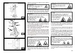
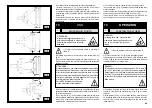
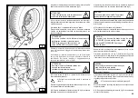
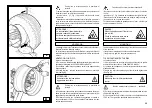
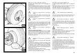
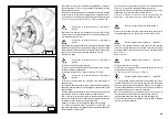
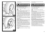
6) Position the bead loosener disk against the second bead of the
tyre and turn the spindle until the clip is at the low point (at 6 o’clock).
7) Move the disk away from the wheel.
8) Remove the clip and replace it at 6 o’clock outside the second
bead (See Fig. N).
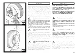
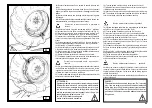
9) Turn the spindle clockwise 90° to bring the clip to 9 o’clock.
10) Move the disk forward until it is about 1-2 cm inside the edge of the
rim. Begin to turn the spindle clockwise checking to make sure that,
with a 90° turn, the second bead begins to slip into the centre well.
11) When the bead is fully mounted, move the tool away from the
wheel, tip it to its non-working position and remove the clip.
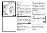
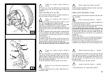
12) Position the platform under the wheel, lower the spindle until the
wheel rests on the platform.
Portarsi con la colonnetta mobile in posizione di
lavoro C.
Take the mobile control unit to work
position C.
6) Posizionare il disco stallonatore contro il secondo tallone del
pneumatico e ruotare l'autocentrante fino a portare la pinza nel punto
più in basso (ore 6).
7) Allontanare il disco stallonatore dalla ruota.
8) Rimuovere la pinza e rimontarla nella medesima posizio-
ne (ore 6) al di fuori del secondo tallone (vedi fig. N).
9) Ruotare l'autocentrante in senso orario di 90° fino a portare la
pinza a ore 9.
10) Avanzare con il disco stallonatore fino a portarsi all'interno del
bordo del cerchio di 1-2 cm avendo cura di rimanere a circa 5 mm
dal profilo.
Iniziare la rotazione in senso orario controllando che, dopo una
rotazione di circa 90°, il secondo tallone inizi a scivolare nel canale
del cerchio.
11) A montaggio ultimato allontanare l'utensile dalla ruota, ribaltarlo
in posizione di fuori lavoro e rimuovere la pinza.
12) Posizionare la pedana sotto la verticale della ruota, abbassare
l'autocentrante fino ad appoggiare la ruota sulla pedana.
13) Chiudere completamente le griffe dell'autocentrante avendo cura
di sostenere la ruota per evitarne la caduta.
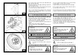
13) Close the arms of the spindle completely. Support the wheel to
prevent it falling off.
14) Traslare la pedana in modo da liberare la ruota dall'autocentrante.
15) Rimuovere la ruota.
N.B.: Nel caso il pneumatico lo consenta si può velocizzare l'operazione
sopra descritta montando entrambi i talloni in una sola volta:
- Procedere come ai punti 1,2,3,4 sopra descritti, ma invece di ag-
ganciare alla pinza il solo primo tallone (vedi punto 4), agganciarli
entrambi.
- Sollevare il cerchio con il pneumatico agganciato e ruotarlo in senso
antiorario di 15-20 cm. (pinza a ore 10).
- Procedere come descritto ai punti 10, 11, 12, 13, 14, 15 di
questo paragrafo.
14) Move the platform to remove the wheel from the spindle.
15) Remove the wheel.
NB: If the tyre permits it, the operation described above can be
speeded up by mounting both beads at the same time:
- Follow the steps described under points 1,2,3,4 described above
but instead of attaching the clip to just the first bead (refer to point
4) clip it to both.
- Lift the rim with the tyre hooked to it and turn it anticlockwise 15-20
cm (clip at 10 o’clock).
- Follow the steps described in points 10,11,12,13,14,15 above.
Take the mobile control unit to work
position B.
Portarsi con la colonnetta mobile in posizione di
lavoro B.
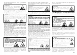
ATTENZIONE !
Questa operazione può essere estremamente pericolosa!
Effettuarla manualmente solo nel caso si sia assolutamente
sicuri di riuscire a mantenere in equilibrio la ruota. Le ruote
non devono mai essere sollevate dall'operatore, si deve farle
rotolare sul pavimento per ruote pesanti oltre 110 kg e/o di
grandi dimensioni (diametro oltre 130
cm) si DEVE utilizzare un adeguato
mezzo di sollevamento meccanico.
DANGER!
This operation can be extremely dangerous. Do it manually
only if you are certain you can keep the wheel balanced.
Heavy tyres (over 110kg) and/or oversize tyres (with diam-
eter over 130cm) shall never be lifted by hand. Let them roll
on floor and lift them by means of an adequate mechanical
lifting device.
Содержание S 551 XL A
Страница 64: ...64 SCHEMA ELETTRICO ELECTRIC DIAGRAM SCHEMA ELECTRIQUE SCHALTPLAN ESQUEMA ELECTRICO 1 110 V 1 ph...
Страница 65: ...65 230 V 1 ph...
Страница 66: ...66 220 V 3 ph...
Страница 67: ...67 400 V 3 ph...
Страница 68: ...68 SCHEMA ELETTRICO ELECTRIC DIAGRAM SCHEMA ELECTRIQUE SCHALTPLAN ESQUEMA ELECTRICO 2...
Страница 72: ......

