12
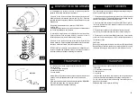
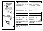
Lo smontagomme universale deve essere installato su un pavimento
di cemento ben livellato di almeno 20 cm di spessore e di una qualità
minima di cemento pari a B25, secondo le normative
DIN 1045 (fondamenta).
Per maggiore chiarezza si veda il disegno a fianco e la tabella sot-
toindicata.
Se le caratteristiche del pavimento sopra menzionato non sono di-
sponibili, si devono predisporre fondazioni sotto ai punti d'appoggio.
La superficie sulla quale lo smontagomme universale sarà installato
deve essere piana in tutte ledirezioni.
Pendenze orizzontali fino a 0.25% possono essere compensate
tramite appositi spessori, cunei o simili.
Operando su ruota di peso superiore a 1000 Kg è
necessario fissare lo smontagomme al pavimento
utilizzando apposite viti di ancoraggio
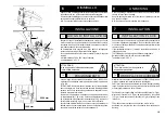
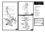
Con una punta in Widia Ø 16, forare il pavimento alla profondità di
almeno 130 mm, passando per i fori già predisposti sul telaio di base.
Se sul pavimento esiste una coperture supplementare (B), oppure
si rendono necessari spessori o cunei per compensare pendenze
del suolo (C), devono essere utilizzate viti di ancoraggio più lunghe.
Inserire in ogni foro il tassello di ancoraggio.
Accertarsi sempre che le viti di ancoraggio penetrino di almeno 125
mm. nella soletta di cemento, come illustrato in figura.
Serrare a fondo le viti di ancoraggio.
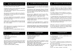
The universal tyre-changer must be installed on a levelled concrete
floor at least 20 cm. thick, with a minimum concrete quality of B25 in
accordance with DIN 1045 requirements (foundations).
For your reference see the side drawing as well as the table herebelow.
If a floor of this type is not available on site, fastening points of the
specified concrete quality are acceptable.
The surface, on which the universal tyre-changer is to be installed,
must be flat and well levelled in all directions.
Inclinations up to 0,25% relative to the horizontal can be compensated
using suitable shims, wedges or the alike.
By means of a Widia bit Ø 16, drill at least 130 mm
into the floor passing through the holes provided on the base frame.
If there is an additional floor covering (B), or if shims or wedges are
necessary for levelling (C), longer anchor bolts must be used.
Place an anchor bolt into each hole.
Make sure the anchor bolts extend at least 125 mm. into the concrete
slab, as indicated in the drawing.
Tighten the anchor bolts fully.
When working with wheels, whose weight is higher
than 1000 kg., it is necessary to fasten the tyre-
changer to the floor by means of proper anchor
bolts.
100
50
150
100
100
ø 8
Terreno
Cemento armato
Griglia elettrosaldata
Strato di ghiaia
Ground
Reinforced concrete
Electrowelded grid
Pebble gravel
Foundations dimensions in cm.
Concrete
quality
Min. pressure
resistence
Length
Width
Thickness
B25
425 Kg / cm
2
200
164
15
Dimensioni fondamenta in cm.
Qualità
del
cemento
Resistenza
minima della
superficie
Lunghezza
Larghezza
Spessore
B25
425 Kg / cm
2
200
164
15
Содержание S 551 XL A
Страница 64: ...64 SCHEMA ELETTRICO ELECTRIC DIAGRAM SCHEMA ELECTRIQUE SCHALTPLAN ESQUEMA ELECTRICO 1 110 V 1 ph...
Страница 65: ...65 230 V 1 ph...
Страница 66: ...66 220 V 3 ph...
Страница 67: ...67 400 V 3 ph...
Страница 68: ...68 SCHEMA ELETTRICO ELECTRIC DIAGRAM SCHEMA ELECTRIQUE SCHALTPLAN ESQUEMA ELECTRICO 2...
Страница 72: ......


