background image

21

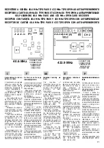
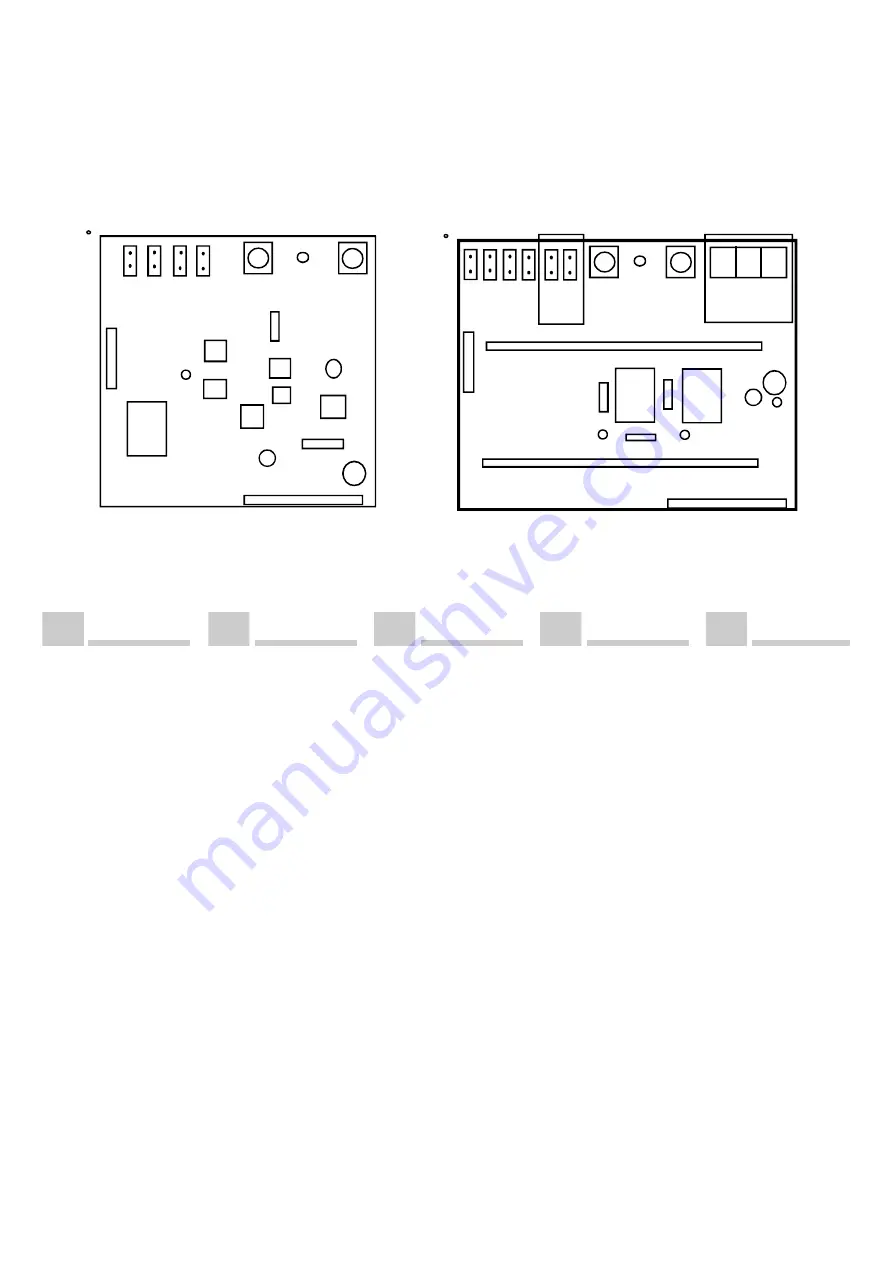
P1

K2

P2

LED

J4

J3 J2

J1

CONNETTORE

CONNECTEUR

CONNECTOR

CONECTOR

J2J4

NC C NO

CH 2

CH 2

K1

433.9 MHz

RICEVITORE A SCHEDA 40.6 MHz TIPO PASS E 433 MHz TIPO OPEN AD AUTOAPPRENDIMENTO
RECEPTEUR A CARTE 40.6 MHz DU TYPE PASS ET 433 MHz DU TYPE OPEN A AUTOAPPRENTISSAGE

SELF-LEARNING 40.6 MHz PASS AND 433 MHz OPEN CARD RECEIVER

RECEPTOR CON TARJETA 40.6 MHz TIPO PASS Y 433 MHz TIPO OPEN CON AUTOAPRENDIZAJE
RECEPTOR DE CARTÃO 40.6 MHz TIPO PASS E 433 TIPO OPEN COM AUTO-APRENDIMENTO

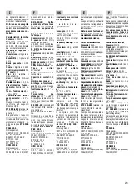
Apprendimento indivi-

duale via radio

L'inserimento via segnale

radio dei codici dei tra-

smettitori avviene tramite

attivazione individuale di

ciascun trasmettitore.

 - Premere il pulsante di

programmazione  

P1

 per

attivare la fase di appren-

dimento.

 - Si accende il led rosso;

ha inizio la fase di pro-

grammazione ed il  ricevi-

tore   è pronto ad appren-

dere i codici dei    trasmet-

titori.

 - Effettuare una trasmis-

sione premendo uno qual-

siasi dei pulsanti del tra-

smettitore.

 - Il led rosso conferma la

memorizzazione del codi-

ce trasmesso con 2 / 3

lampeggi;  terminati  i lam-

peggi il led rimane  nuova-

mente acceso, ed è possi-

bile ripetere la procedura

con un altro trasmettito-

re.

- Memorizzare tutti i tra-

smettitori effettuando una

trasmissione con ognu-

no di essi. Al termine dell'

operazione premere nuo-

vamente il pulsante di pro-

Individual  learning  via

radio

The insertion of

transmitter codes via ra-

dio signals takes place by

means of the individual

activation of each

transmitter.

- Press the programming

button 

P1

 to activate the

learning phase.

- The red led lights up; the

programming phase

begins, and the receiver is

ready to learn the

transmitter codes.

-Perform the transmission

by pressing any one of the

transmitter' s buttons.

- The red led confirms that

the trasmitted code has

been memorized by

flashing 2/3 times. When

it has finished flashing the

led remains lit up, and it is

possible to repeat the pro-

cedure with another

transmitter.

- Memorize all the

transmitters by carrying

out a transmission with

each of them.

- At the end of the

operation press the

programming button 

P1

again to exit the procedu-

CONECTOR

A u t o a p p r e n t i s s a g e

individuel par radio

La mémorisation par signal

radio des codes des émetteurs

se fait par l' activation de

chaque émeteur.

- Appuyer sur la touche de

programmation  

P1

  pour

commencer la   phase d'

apprentissage.

- Le voyant rouge s' allume. La

phase de programmation

commence et le récepteur est

prêt pour  apprendre les codes

des émetteurs.

- Appuyer sur l' une des

touches de l' emetteur pour

effectuer une transmission.

- Le voyant rouge clignote 2

ou 3 fois pour confirmer la

mémorisation du code émis;

aprés quoi le voyant reste

allumé. A ce moment-là, il est

possible de répéter la proce-

dure avec un autre émetteur.

-Effectuer une transmission

avec chaque émetteur pour

les mémoriser tous.

- Effectuer une transmission

avec chaque émetteur pour

les mémoriser tous.

A la fin de cette opération,

appuyer  de  nouveau  sur 

 la

Aprendimento individual via

rádio

A introdução por sinal via

rádio dos códigos dos

transmissores é feita

mediante activação individual

de cada transmissor.

- Premer o botão de

programação 

P1

 para activar

a fase de aprendimento.

- Acende-se o led vermelho;

inicia a fase de programação

e o receptor está pronto para

receber os códigos dos

transmissores.

- Efectuar uma transmissão

premendo qualquer um dos

botões do transmissor.

- O led vermelho confirma a

memorização do código

transmitido com 2/3

relâmpagos e o led

permanece novamente aceso,

sendo possível repetir o

procedimento com um outro

transmissor.

“Memorizar todos os

transmissores efectuando

uma transmissão com cada

um deles.

- No final da operação, para

sair da programação    premer

Aprendizaje individual

por radio

La introducción por señal

radio de los código de los

transmisores se lleva a

cabo mediante la

activación individual de

cada transmisor.

-Alimentar correctamente

el receptor.

- Pulsar el botón de

programación  

P1

  para

activar la fase de

aprendizaje.

- Se enciende el led rojo;

ha iniciado la fase de

programación y el receptor

está listo para aprender

los códigos de los

transmisores.

- Efectuar una trasmisión

pulsando uno cualquiera

de los botones del

transmisor.

- El lrd rojo confirma la

memorización del código

transmitido mediante 2/3

parpadeos; una vez

terminados los mismos,

el led permanece

encendido, y es posible

repetir el procedimiento

con otro transmisor.

- Memorizar todos los

transmisores efectuando

una   transmisión  con

cada  uno de ellos.

CONECTOR

P1

K1

P2

LED

J4

J3

J2

J1

CONNETTORE
CONNECTEUR

CONNECTOR

CONECTOR

40.6 MHz

I

F

UK

E

P

Содержание PASS 3

Страница 1: ...POUR LE MONTAGE INSTRUCTIONS FOR INSTALLATION INSTRUCCIONES PARA EL MONTAJE INSTRUÇÕES DE INSTALAÇÃO ISO 9002 Cert n 0079 MOTORIDUTTORE PASS 3 12 VDC CON APPARECCHIATURA ELETTRONICA INCORPORATA DG MOTOREDUCTEUR PASS 3 12 VDC AVEC PLATINE ELECTRONIQUE INCORPOREE DG MOD PASS 3 12 VDC GEARMOTOR WITH A BUILT IN DG ELECTRONIC CONTROL UNIT MOTORREDUCTOR PASS 3 12 VDC CON EQUIPO ELECTRONICO INCORPORADO D...

Страница 2: ...ruc tions in this handbook before starting installation of the product Incorrect installation may cause damage to persons animals or things for which Gi Bi Di cannot be held responsible Before connecting the instrument ensure that the rating indicated on the plate corresponds to that of the mains Do not install the product in an explosive environment the presence of inflammable gas or fumes consti...

Страница 3: ... switch must be fitted with a contact opening distance equal to or greater than 3 mm Check that upstream of the electrical system a differential switch with a threshold of 0 03A is installed Connect the automation to an efficient earthing system as provided by the safety regulations in force Gi Bi Di declines all responsibility for the safety and good functioning of the automation in case the comp...

Страница 4: ...t switch it off abstaining from any attempt at repair or direct inter vention and contact qualified technicians only Inobservance of the above may create dangerous conditions Before carrying out any cleaning maintenance or repair operations disco nnect the automation from the mains and any emer gency batteries To guarantee efficiency of the system and its proper func tioning it is indispensable to...

Страница 5: ...otor 2 Two pairs of modulated infrared photocels one internal and one external 3 Antenna 4 Pneumatic strip 5 Push button panel 6 Rack 7 Key selector 8 Screened coaxial cable 9 Power supply line to equipment follow regulations in force 10 12 V flashing light WARNING It is important that an omnipolar magneto thermal switch with a contact opening of minimum 3 mm is installed on the power supply line ...

Страница 6: ...TORE MONTAGE DU MOTOREDUCTEUR INSTALLATION OF THE GEARMOTOR MONTAJE DE EL MOTORREDUCTOR MONTAGEM DO MOTORREDUTOR Dimensioni di ingombro in mm Dimensions en mm Overall dimensions are in mm Dimensiones máximas en mm Dimensões em mm ...

Страница 7: ...heavy sheaths of the correct dimensions to protect the cables The sheaths have to be covered by cement 4 5 6 7 8 9 10 Electrical cables see page 5 Fastening plate which allows the gearmotor height to be adjusted Tube for laying down the cable Brackets that allows horizontal adjustement of the gearmotor Nuts Gearmotor Electronic control unit E MAMPOSTERÍA DE LA PLACA DE ANCLAJE DEL MORORREDUCTOR 1 ...

Страница 8: ...ts in the drawing are in mm Figuras 1 2 y 4 Montaje de la cremallera NOTA Las cotas del gráfico están en mm Figuras 1 2 e 4 Montagem da cremalheira N B Dimensões em mm Figura 3 Gioco minimo tra ingranaggio e cremagliera Figure 3 Jeu minimum entre l engrenage et la crémaillere Fig 3 Minimum play between the gear and the rack Figura 3 Jeugo mínimo entre engranaje y cremallera Fig 3 Folga mínima entr...

Страница 9: ...r must not be less than 15 mm Place the magnets 2 so that they exactly correspond horizontally with the small magnet 1 installed on the card The magnets 2 are polarized differently from each other one has negative polarization and other has positive polarization Therefore you have to check the installation of the two magnets on the brackets 5 To do this you have to check the stopping points of the...

Страница 10: ...the key 3 and turn it clockwise to the right without forcing it The key 3 will be pushed out a few millimeters by a spring Then completely turn the handle 1 180 towards the left You can now manually open and close the gate To automatically reset it turn the handle 1 to its initial position push the key 3 forward turn it counterclockwise to the left and then remove it NOTE If the key 3 is not compl...

Страница 11: ...11 4 APPARECCHIATURAELETTRONICA PLATINE ÉLECTRONIQUE CONTROL PANEL APARATO ELECTRONICO APARELHAGEM ELECTRÓNICA ...

Страница 12: ...ante P2 a questo punto la programmazione è memorizzata ed il display visualizzerà 2 cioè la funzione successiva programmabile Per effettuare la programmazione di 2 eseguire le operazioni pre cedenti Se si desidera passare ad altra programmazione premere il pulsante di incremento P1 ed il display avanzerà 3 4 5 ecc Dopo aver programmato tutte le funzioni desiderate uscire dalla programmazione con i...

Страница 13: ...O PEDONALE 9 6 0 Comando sequenziale di apertura pausa chiusura stop apertura ecc 1 Comando sequenziale di apertura pausa chiusura apertura ecc 2 Comando sequenziale di apertura chiusura apertura ecc 3 Comando di sola apertura la chiusura potrà essere automatica o comandata dal pulsante di chiusura TEMPO DI PASSAGGIO PEDONALE Regolabile da 0 a 99 secondi PULSANTE DI START 8 6 0 Comando sequenziale...

Страница 14: ...lsante di stop se il cancello non è a finecorsa chiusura la lampada rimane accesa LAMPEGGIATORE 20 18 0 Uscita a luce fissa si accende all inizio della fase di apertura si spegne in pausa e si riaccende all inizio della fase di chiusura 1 Uscita a luce fissa si accende all inizio della fase di apertura si spegne in pausa e si riaccende all inizio della fase di chiusura ma è possibile inserire un p...

Страница 15: ...Con il pulsante di incremento P1 è possibile selezionare l allocazione di memoria desiderata e cancellare il codice del trasmettitore in essa contenuta premendo il pulsante P2 MEMORIZZAZIONE CODICI TRASMETTITORI Selezionando ed entrando in questa programmazione viene visualizzato la prima allocazione di memoria libera Per memorizzare il codice di un trasmettitore selezionare con il pulsante P1 l a...

Страница 16: ...une batterie de 12 V connecter à la borne 3 le positif connecter à la borne 4 le négatif Fils communs pour boutons poussoirs contacts cellules photoélectriques témoin lumineux et lumière intermittente Contact N A du bouton poussoir de fermeture Contact N A du bouton poussoir de start ouverture voir paragraphe programmation Contact N A du bouton poussoir de passage piétonnier Contact N C de la cell...

Страница 17: ...ase de fermeture la barre palpeuse est inactive 2 Si elle est interceptée pendant la phase d ouverture elle arrête et inverse le mouvement en fermeture pendant 2 secondes la lumière intermittente reste allumée et le portail n effectue aucune manoeuvre tant qu une impulsion de start ne se produit pas qui fait repartir le portail en ouverture Pendant la phase de fermeture la barre palpeuse est inact...

Страница 18: ...ure ou à la fin du temps de service En appuyant sur le bouton poussoir stop si le portail n est pas en fin de course fermeture le témoin reste allumé 2 Il clignote lentement pendant la phase d ouverture s allument en pause clignote rapidement pendant la phase de fermeture Le témoin s éteint en fin de course fermeture ou à la fin du temps de service En appuyant sur le bouton poussoir stop si le por...

Страница 19: ...écute les mêmes fonctions que le poussoir de fermeture bornes 7 6 PROGRAMMATION TOUCHE 1 DE L EMETTEUR 0 Exécute les mêmes fonctions que le poussoir de start bornes 8 6 1 Exécute les mêmes fonctions que le poussoir de passage piétonnier bornes 9 6 2 Exécute les mêmes fonctions que le poussoir de fermeture bornes 7 6 EFFACEMENT DES CODES EMETTEURS En sélectionnant et en entrant dans cette programma...

Страница 20: ... display will scroll forward 3 4 5 etc After having programmed all the desired functions exit from programming with the increase key P1 until the display turns off In case of error the program can always be cancelled and the standard default stored by entering the programming menu selecting the number 9 9 and confirming with the P2 key If a manual manoeuvre of the gate is carried out ensure that w...

Страница 21: ...ial open pause close stop open etc command 1 Sequential open pause close open etc command 2 Sequential open close open etc command 3 Open only command closing may be automatic or controlled by the closing button 4 DEAD MAN S LOGIC function The button executes opening only if it is held pressed down Closing may be controlled by holding the closing button pressed down Should any safety device interv...

Страница 22: ...osing phase 2 Fixed light output it comes on at the beginning of the opening phase goes off during pause and comes on again at the beginning of the closing phase however a pre flashing may be set during the closing and opening phase 3 Fixed light output the flashing light comes on at the beginning of the opening phase remains on during pause and goes off at the end of closing 4 Same function as 0 ...

Страница 23: ...nd entering this program the first memory allocation containing a code is displayed With the increase button P1 the desired memory allocation may be selected and the transmitter code contained in it deleted by pressing the button P2 TRANSMITTER CODE STORAGE Selecting and entering this program the first free memory allocation is displayed To store the transmitter code select the desired memory allo...

Страница 24: ...tón P2 con ello la programación es almacenada y en el monitor se visualizará 2 esto es la sucesiva función programable Para efectuar la programación de 2 se deberán aplicar las funciones precedentes En caso de que se desee pasar a otra programación oprimir el botón de incremento P1 y el monitor avanzará 3 4 5 etc Después de haber programado todas las funciones elegidas salir de la programación med...

Страница 25: ...umpe e invierte el movimiento que pasa a ser de cierre durante 2 segundos la luz intermitente permanecerá encendida y la cancela no efectuará ninguna maniobra mientras no llegue un impulso de arranque el que hará partir nuevamente la cancela en apertura En fase de cierre la banda no está activada BOTÓN DE PASO PEATONAL 8 6 0 Mando secuencial de apertura pausa cierre parada apertura etc 1 Mando sec...

Страница 26: ... final del tiempo de trabajo Oprimiendo el botón de parada si la cancela no está en final de carrera cierre la lámpara permanece encendida 2 Centellea lentamente en fase de apertura se enciende en pausa centellea velozmente en fase de cierre La lámpara se apaga en el final de carrera de cierre o al final del tiempo de trabajo Oprimiendo el botón de parada cuando la cancela no está en final de carr...

Страница 27: ...bornes 7 6 PROGRAMACIÓN TECLA 1 DEL TRANSMISOR 0 Cumple las mismas funciones del botón de arranque bornes 8 6 1 Cumple las mismas funciones del botón de paso peatonal bornes 9 6 2 Cumple las mismas funciones del botón de cierre bornes 7 6 CANCELACIÓN CÓDIGOS TRANSMISORES Seleccionando y entrando en esta programación se visualiza la primera asignación de memoria que contiene un código Con el botón ...

Страница 28: ...o o botão P2 nesta altura a programação é guardada na memória e o mostrador passa a exibir 2 ou seja a próxima função que poderá ser programada Para a programação da função 2 efectuar as operações anteriores Desejando passar para outra programação pressionar o botão de incremento P1 fazendo assim avançar o mostrador para 3 4 5 etc Depois de se terem programado todas as funções desejadas sair da pr...

Страница 29: ... á um impulso de start que fará partir de novo o portão com movimento de abertura A banda sensível não está activa durante a fase de encerramento do portão 2 Se interceptada durante a fase de abertura interrompe e inverte o movimento durante 2 segundos a lâmpada pisca pisca ficará acesa e o portão não efectuará qualquer manobra enquanto não lhe chegar um impulso de start que o fará partir de novo ...

Страница 30: ...isca durante a fase de encerramento e só se apaga no final da excursão de encerramento do portão ou no fim do tempo de trabalho Se se carregar no botão de stop sem o portão ter atingido o fim de curso de encerramento a lâmpada mantém se acesa 2 Pisca lentamente durante a fase de abertura do portão acende se durante a pausa pisca rapidamente durante a fase de encerramento A lâmpada apaga se no fim ...

Страница 31: ...o botão de passagem de peões terminais 9 6 2 Exerce as mesmas funções do botão de encerramento terminais 7 6 PROGRAMAÇÃO DO BOTÃO 1 DO TRANSMISSOR 0 Exerce as mesmas funções do botão de start terminais 8 6 1 Exerce as mesmas funções do botão de passagem de peões terminais 9 6 2 Exerce as mesmas funções do botão de encerramento terminais 7 6 CANCELAMENTO DOS CÓDIGOS DOS TRANSMISSORES Seleccionando ...

Страница 32: ...noltre dichiara che non è consentito mettere in servizio il macchinario fino a che la macchina in cui saranno incorpo rati o di cui diverranno componenti sia stata identificata e ne sia stata dichiarata la conformità alle condizioni della Direttiva 89 392 CEE e alla legislazione nazionale che la traspone vale a dir fino a che il macchinario di cui alla presente dichiarazione non formi un complesso...

Страница 33: ... ne forme un tout avec la machine finale Poggio Rusco le 1 Juin 1998 Administrateur Delegué Tiziano Toselli CE DECLARATION OF CONFORMITY FOR MACHINES Directive 89 392 EEC Attachment II part B PROHIBITION OF OPERATION The manufacturer Gi Bi Di Continental Srl Via Abetone Brennero 177 B I 46025 Poggio Rusco MN declares that the products GEARMOTOR PASS 3 are constructed to be incorporated in a machin...

Страница 34: ...ente declaración forme un conjunto único con la máquina final Poggio Rusco 01 de Junio de 1998 Admistrador Delegado Tiziano Toselli DECLARAÇÃO DE CONFORMIDADE PARA MÁQUINAS Directiva 89 392 CEE Anexo II parte B PROIBIÇÃO DE ENTRADA EM SERVIÇO O Fabricante Gi Bi Di Continental Srl Via Abetone Brennero 177 B I 46025 Poggio Rusco MN Declara que o produto MOTORREDUTOR PASS 3 são fabricados para serem ...

Страница 35: ...dividuelparradio La mémorisation par signal radiodescodesdesémetteurs se fait par l activation de chaqueémeteur Appuyer sur la touche de programmation P1 pour commencer la phase d apprentissage Levoyantrouges allume La phase de programmation commenceetlerécepteurest prêtpourapprendrelescodes desémetteurs Appuyer sur l une des touches de l emetteur pour effectuerunetransmission Levoyantrougeclignot...

Страница 36: ...un émetteur est mis en mémoire les10secondssont remisesàzéro IL EST POSSIBLE DE MEMORISER 50 CODES DIFFERENTSAUTOTAL Sélection des canaux Pourprogrammerlecanalde réceptionduréceptorilfaudra agir sur les cavaliers J1 J2 J3 etJ4delafaçonsuivante joindre J1 pour valider le fonctionnementdurécepteur sur le canal n 1 joindre J2 pour valider le fonctionnementdurécepteur sur le canal n 2 joindre J3 pour ...

Страница 37: ...e saída mono estável Saída contacto N A no conector Capacidade contacto 0 5 A V i s u a l i z a ç ã o funcionamento medianteled vermelho Temp de funcionamen to 15 55 C Temp de armazena gem 40 85 C Este rádio receptor é conforme às seguintes Directivas CEE ETS 300 683 relativa à C o m p a t i b i l i d a d e Electromagnética Corresponde aos requisitos técnicos relativos às instalações radioeléctric...

Страница 38: ...annelli pieni non devono risultare di spessore 5 5 1 5 1 1 5 1 2 5 2 5 2 1 5 2 2 5 3 5 3 1 5 3 2 5 4 5 4 1 5 4 1 1 5 4 1 2 5 4 1 3 5 5 5 5 1 5 5 2 5 2 3 6 6 1 3 6 1 3 1 6 1 3 2 6 1 3 3 6 1 4 6 1 4 1 6 1 4 2 6 1 4 4 6 1 5 6 1 6 A1 2 1 A1 2 2 minore di 0 6 mm quelle impiegate nelle strutture portanti non devono risultare di spessore minore di 2 mm DISPOSITIVI DI PROTEZIONE La costola a bordo sensibi...

Отзывы: