21
Optima 300
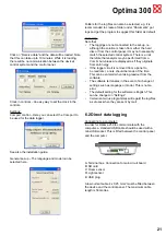
Click on “Receive data” and the data will be loaded. Note
that this can take up to 10 minutes. While it is loading,
there will be no communication between the device’s
control system and the control panel.
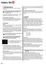
Clock in controls – An easy way to set the clock in the
controls.
Settings:
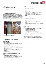
Comport control – Here you can select the Com-port to
be used for the data logger.
See also the installation guide.
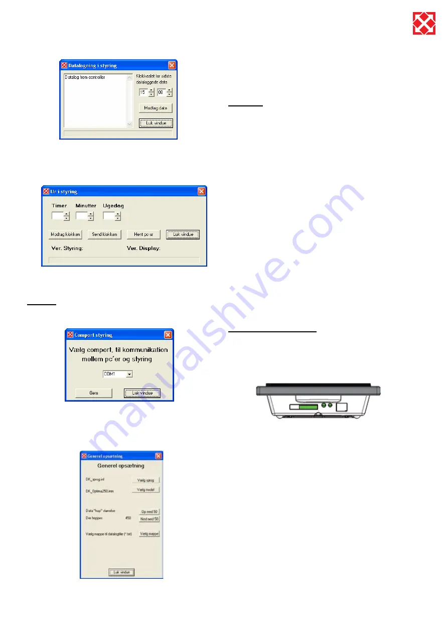
General set-up – The language and model can be
selected here.
Folders for the log files can also be selected, e.g. it is
recommended to create a folder under “Documents” got
logs and get the program to suggest this folder as default.
Generally:
Note that:
The loggings are not connected to the set-up, i.e.
•
although the solution is taken from either the hard
disc or from the control panel, it may not necessarily
match the selected control system. There is a risk
therefore that analysis may be performed from a
Combi, but values are displayed as if they originate
from an Energy.
If the logger circuit is removed from a panel to
•
be read later, a note should be made of the time.
This can be entered when taking readout from the
software.
The software terminates in the event of a change of
•
settings such as language or model. This is not an
error.
The default setting for the software is English. This
•
can be changed in “Settings”.
Certain anti-virus programmes will regard the log-files
•
as viruses when they are sent by mail.
6.2 Direct data logging
Connecting to a computer:
In order for Optima 250 to communicate with the
computer, a standard USB cable should be used with a
mini-USB socket. This is fitted between the control panel
and the computer.
A: Terminal box. Connection to main circuit board
B: SD card
C: Room sensor
D: Light sensor
E: USB plug
A low current cable 4 x 0.25 mm2 must be fitted between
the device and the control panel. The maximum cable
length is 50 metres.


