22
Optima 300
7. Maintenance
Follow the following instructions to achieve optimal
performance:
Before opening the device, turn off the power,
pull out the plug and wait until the fan is
completely quiet.
After installing for the first time, check after a couple of
days that the condensation outlet is working.
Environmental requirements:
When repairing or dismantling the device, statutory
environmental regulations must be observed regarding
recycling and destruction of various materials.
7.1 Device
Filters:
The filters must be changed when “change filter” flashes
in the control panel display.
Use the device’s circuit breaker to stop the device or use
the circuit breaker on the terminal box. Open the front
and remove the filters. Reset the filter timer when the
filters have been changed. You can make an adjustment
in the operating menu if you wish to change the filters
with a different time interval
.
There is a danger of cuts from sharp discs. The
discs must not be damaged.
Vacuum cleaning or using pressurised air
on the filters is not recommended. Filter
performance may be impaired.
Condensation water and condensation outlet:
The condensation trays must be cleaned of dirt every
autumn. Fill the condensation trays with water and check
that the water drains away. If not, the outlets must be
cleaned. Check that the vaporisor discs are also clean.
Heat exchangers:
The heat exchangers should be inspected every 3 years.
If it is dirty, remove it and wash it in warm water with soap
and rinse with a hand shower.
Fans:
Inspect the fans every three years for dirt in the fan
wheels. Remove the front cover from the device. Clean
the fans with a brush, a bottle cleaner or a paint brush.
Make sure that the counterbalancing weights on the fan
wheels are not removed, as this will lead to disequilibrium
and cause a higher level of noise and also cause wear to
the fans.
Air supply and extraction valves:
Clean the valves by drying with a dry cloth. Take care that
the valve does not turn around, causing a change in air
volume.
7.2 Alarms
Filter timer:
The control system has a filter timer in order to ensure
that the filters are changed and optimal performance
is maintained. When the timer reaches the configured
value, “change filter” will flash in the display until the filter
has been changed. When the filter has been changed,
the screen image for daily operations will return. Hold
down the button for the filter symbol until the exclamation
mark disappears and the device returns to normal
running.
Data error:
This error message will appear if no communication is
possible between the display and the control system.
Check that the cable connection is correct on terminals
21 to 24.
21 = Signal
22 = Signal
23 = 10 Volt
24 = 0 Volt
Frost alarm:
This error message will be displayed if a water heat
surface is fitted to the system and the temperature on the
water heat surface is too low, causing a danger of frost
burst. The control system will stop the device and open
the motor-operated valve to keep the water service warm.
Pressure switch error:
When the high-pressure switch disengages, “Pressure
switch” will appear flashing in the display until the
pressure switch’s red reset button is activated.
7.3 Dismantling/ decommissioning the
device
The following must be performed:
The power supply, i.e. the electric cables, must
be disconnected from the device. Disconnect the
condensation outlet and power cables to any after-heat/
pre-heat. Disconnect wires for the panel and remove
channels. If the device is to be decommissioned, the
cables must be removed to avoid condensation water in
the device and in the channels. Close all air supply and
extraction valves.
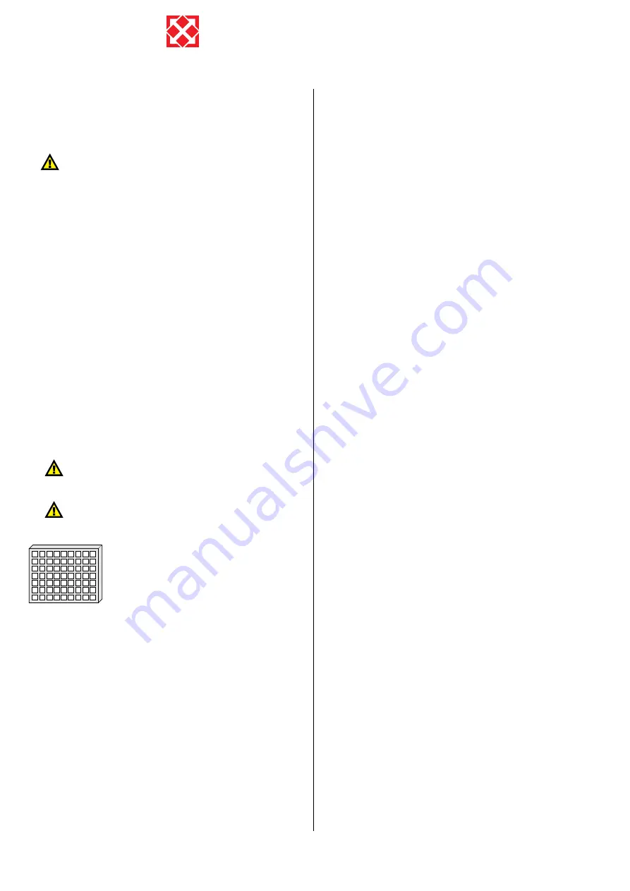
G4 = Standard filter (Coarse filter class G4).
F5 = Fine filter (Fine filter class F5).
F7 = Fine filter (Fine filter class F7).


