4
Optima 300
2. Installation
2.1 Installation of the control panel
The control panel is intended for hanging on a wall. The
control panel must be positioned in the home at a height
of about 1.5 metres from the floor. The control panel must
not be countersunk into the wall, since the panel also
functions as a room thermostat. It is also equipped with
a light sensor. The control panel must not be exposed to
direct sunlight. It must not be mounted on an outer wall or
the room sensor will not be able to measure the correct
room temperature and the light sensor will not regulate
the light in the display correctly. It is also recommended
that you do not place a lamp underneath the control panel
as this may also affect the light sensor.
2.2 Mounting
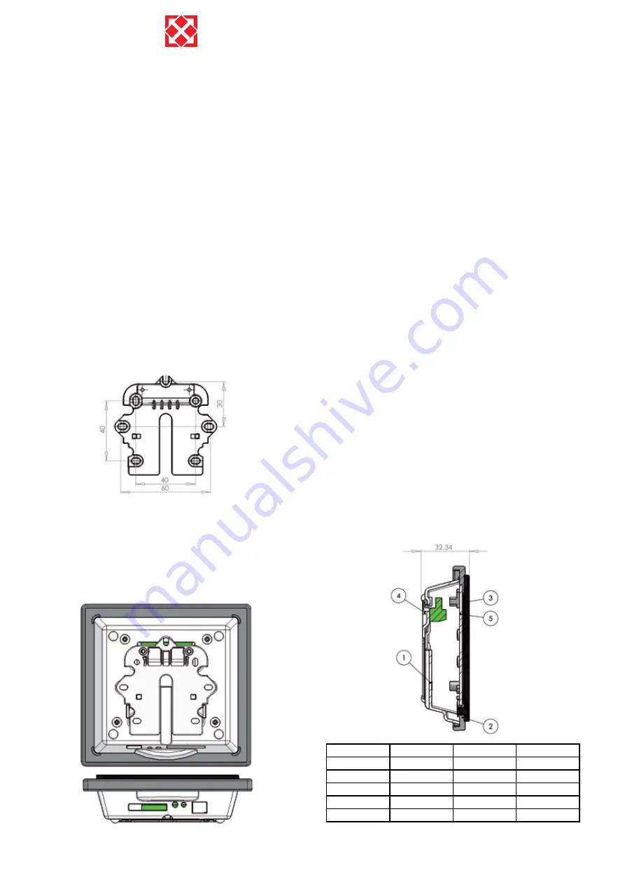
Find the place where the control panel is to be mounted,
mark the places for the holes and screw the fitting onto
the wall.
Hold the wall frame against the wall and mark the holes
for mounting the frame. Drilling of holes, the size of the
holes and the corresponding screws for mounting will all
depend on the wall material.
Place the control panel down into the fittings and tip it in
against the wall.
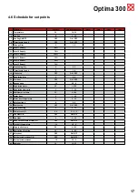
At the bottom of the control panel there is access to:
A: Terminal board. Connection to main circuit board
B: SD card
C: Room sensor
D: Light sensor
E: USB port
Fit a low-voltage cable 4 x 0.25 mm² between the unit
and the control panel. The maximum cable length is
50 m. The voltage drop will be too great if the cable
is over 50 m long and this may produce operational
disturbances.
The wall fixture can be mounted in two ways:
Screw the fixture on to a smooth wall and lead the
1.
cable up from below so that it is visible.
Fit a masonry junction box or a countersunk box to
2.
e.g. a plaster wall. If another type of box is preferred,
to must be ensured that the screw hole match.
Connect the low-voltage cable to the terminal box. Check
that the cable is connected to the same numbers at both
ends. (Between the control panel and the main circuit
board in the unit)
Clip the control panel onto the wall fixture by moving
it downwards a little bit out at the bottom and finish by
pressing it in at the bottom so that it is flush with the wall.
To dismantle, pull the control panel out slightly at the
bottom and lift it up.
Pos.
Amount
Product no.
Description
1
1
069014
House for panel
2
1
069015
Front for panel
3
1
069016
Plate for display
4
1
069012
Wall fittings
5
1
069017
Glas for display


