


Section 3 • Scheduled Maintenance Procedures
November 2014
3 - 14
GS-2669 RT • GS-3369 RT • GS-4069 RT
Part No. 229753
CHECKLIST
A
PROCEDURES
A-13
Drain the Fuel Filter/ Water
Separator - Kubota Diesel
Models
Genie specifications require that this procedure be
performed every 200 hours or monthly, whichever
comes first.
Proper maintenance of the fuel filter/water separator
is essential for good engine performance. Failure to
perform this procedure can lead to poor engine
performance and component damage.
Explosion and fire hazard. Engine
fuels are combustible. Perform this
procedure in an open, well-
ventilated area away from heaters,
sparks, flames and lighted
tobacco. Always have an
approved fire extinguisher within
easy reach.
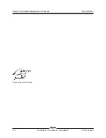
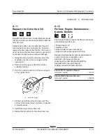
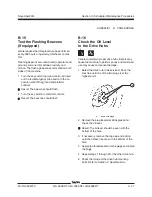
1 Locate the fuel filter/water separator and loosen
the vent plug located on the fuel filter/water
separator head.
2 Loosen the drain plug located at the bottom of
the bowl. Allow the water to drain into a suitable
container until fuel starts to come out.
Immediately tighten the drain plug.
a
head bolt
b
vent plug
c
separator head
d
filter bowl
e
drain plug
3 Tighten the vent plug and clean up any spills or
wet surfaces.
Note: If the fuel bowl is completely drained, you
must prime, or bleed, the fuel filter/water separator
before starting the engine. See
step 5.
4 Start the engine from the ground controls and
check the fuel filter/water separator for leaks.
a
c
b
d
e
Содержание GS-2669 RT
Страница 168: ...Section 6 Schematics November2014 6 8 GS 2669 RT GS 3369 RT GS 4069 RT PartNo 229753 This page intentionally left blank ...
Страница 169: ...Section 6 Schematics November2014 6 9 Control Panel Circuit Diagram 6 10 ...
Страница 171: ...Section 6 Schematics November2014 6 11 Electrical Schematic GS 2669 RT and GS 3369 RT Gas LPG Models ANSI CSA 6 12 ...
Страница 174: ...November2014 Section 6 Schematics 6 14 6 13 Electrical Schematic GS 2669 RT and GS 3369 RT Gas LPG Models ANSI CSA ...
Страница 175: ...Section 6 Schematics November2014 6 15 Ground Control Box Layout GS 2669 RT and GS 3369 RT Gas LPG Models ANSI CSA 6 16 ...
Страница 179: ...Section 6 Schematics November2014 6 19 Electrical Schematic GS 2669 RT and GS 3369 RT Diesel Models ANSI CSA 6 20 ...
Страница 182: ...November2014 Section 6 Schematics 6 22 6 21 Electrical Schematic GS 2669 RT and GS 3369 RT Diesel Models ANSI CSA ...
Страница 183: ...Section 6 Schematics November2014 6 23 Ground Control Box Layout GS 2669 RT and GS 3369 RT Diesel Models ANSI CSA 6 24 ...
Страница 187: ...Section 6 Schematics November2014 6 27 6 28 Electrical Schematic GS 2669 RT and GS 3369 RT Gas LPG Models AS ...
Страница 190: ...November2014 Section 6 Schematics 6 30 6 29 Electrical Schematic GS 2669 RT and GS 3369 RT Gas LPG Models AS ...
Страница 191: ...Section 6 Schematics November2014 6 31 Ground Control Box Layout GS 2669 RT and GS 3369 RT Gas LPG Models AS 6 32 ...
Страница 194: ...November2014 Section 6 Schematics 6 34 6 33 Platform Control Box Layout GS 2669 RT and GS 3369 RT Gas LPG Models AS ...
Страница 195: ...Section 6 Schematics November2014 6 35 Electrical Schematic GS 2669 RT and GS 3369 RT Diesel Models AS 6 36 ...
Страница 198: ...November2014 Section 6 Schematics 6 38 6 37 Electrical Schematic GS 2669 RT and GS 3369 RT Diesel Models AS ...
Страница 199: ...Section 6 Schematics November2014 6 39 6 40 Ground Control Box Layout GS 2669 RT and GS 3369 RT Diesel Models AS ...
Страница 202: ...November2014 Section 6 Schematics 6 42 6 41 Platform Control Box Layout GS 2669 RT and GS 3369 RT Diesel Models AS ...
Страница 203: ...Section 6 Schematics November2014 6 43 Electrical Schematic GS 2669 RT and GS 3369 RT Gas LPG Models CE 6 44 ...
Страница 206: ...November2014 Section 6 Schematics 6 46 Electrical Schematic GS 2669 RT and GS 3369 RT Gas LPG Models CE 6 45 ...
Страница 207: ...Section 6 Schematics November2014 6 47 6 48 Ground Control Box Layout GS 2669 RT and GS 3369 RT Gas LPG Models CE ...
Страница 210: ...November2014 Section 6 Schematics 6 50 Platform Control Box Layout GS 2669 RT and GS 3369 RT Gas LPG Models CE 6 49 ...
Страница 211: ...Section 6 Schematics November2014 6 51 6 52 Electrical Schematic GS 2669 RT and GS 3369 RT Diesel Models CE ...
Страница 214: ...November2014 Section 6 Schematics 6 54 Electrical Schematic GS 2669 RT and GS 3369 RT Diesel Models CE 6 53 ...
Страница 215: ...Section 6 Schematics November2014 6 55 6 56 Ground Control Box Layout GS 2669 RT and GS 3369 RT Diesel Models CE ...
Страница 218: ...November2014 Section 6 Schematics 6 58 Platform Control Box Layout GS 2669 RT and GS 3369 RT Diesel Models CE 6 57 ...
Страница 219: ...Section 6 Schematics November2014 6 59 6 60 Electrical Schematic GS 4069 RT Gas LPG Models ANSI CSA ...
Страница 222: ...November2014 Section 6 Schematics 6 62 6 61 Electrical Schematic GS 4069 RT Gas LPG Models ANSI CSA ...
Страница 223: ...Section 6 Schematics November2014 6 63 6 64 Ground Control Box Layout GS 4069 RT Gas LPG Models ANSI CSA ...
Страница 226: ...November2014 Section 6 Schematics 6 66 6 65 Platform Control Box Layout GS 4069 RT Gas LPG Models ANSI CSA ...
Страница 227: ...Section 6 Schematics November2014 6 67 6 68 Electrical Schematic GS 4069 RT Diesel Models ANSI CSA ...
Страница 230: ...November2014 Section 6 Schematics 6 70 6 69 Electrical Schematic GS 4069 RT Diesel Models ANSI CSA ...
Страница 231: ...Section 6 Schematics November2014 6 71 6 72 Ground Control Box Layout GS 4069 RT Diesel Models ANSI CSA ...
Страница 234: ...November2014 Section 6 Schematics 6 74 6 73 Platform Control Box Layout GS 4069 RT Diesel Models ANSI CSA ...
Страница 235: ...Section 6 Schematics November2014 6 75 6 76 Electrical Schematic GS 4069 RT Gas LPG Models AS ...
Страница 238: ...November2014 Section 6 Schematics 6 78 Electrical Schematic GS 4069 RT Gas LPG Models AS 6 77 ...
Страница 239: ...Section 6 Schematics November2014 6 79 6 80 Ground Control Box Layout GS 4069 RT Gas LPG Models AS ...
Страница 242: ...November2014 Section 6 Schematics 6 82 Platform Control Box Layout GS 4069 RT Gas LPG Models AS 6 81 ...
Страница 243: ...Section 6 Schematics November2014 6 83 Electrical Schematic GS 4069 RT Diesel Models AS 6 82 ...
Страница 246: ...November2014 Section 6 Schematics 6 86 Electrical Schematic GS 4069 RT Diesel Models AS 6 85 ...
Страница 247: ...Section 6 Schematics November2014 6 87 6 88 Ground Control Box Layout GS 4069 RT Diesel Models AS ...
Страница 250: ...November2014 Section 6 Schematics 6 90 Platform Control Box Layout GS 4069 RT Diesel Models AS 6 89 ...
Страница 251: ...Section 6 Schematics November2014 6 91 Electrical Schematic GS 4069 RT Gas LPG Models CE 6 92 ...
Страница 254: ...November2014 Section 6 Schematics 6 94 Electrical Schematic GS 4069 RT Gas LPG Models CE 6 93 ...
Страница 255: ...Section 6 Schematics November2014 6 95 6 96 Ground Control Box Layout GS 4069 RT Gas LPG Models CE ...
Страница 258: ...November2014 Section 6 Schematics 6 98 Platform Control Box Layout GS 4069 RT Gas LPG Models CE 6 97 ...
Страница 259: ...Section 6 Schematics November2014 6 99 6 100 Electrical Schematic GS 4069 RT Diesel Models CE ...
Страница 262: ...November2014 Section 6 Schematics 6 102 Electrical Schematic GS 4069 RT Diesel Models CE 6 101 ...
Страница 263: ...Section 6 Schematics November2014 6 103 6 104 Ground Control Box Layout GS 4069 RT Diesel Models CE ...
Страница 266: ...November2014 Section 6 Schematics 6 106 Platform Control Box Layout GS 4069 RT Diesel Models CE 6 105 ...
Страница 267: ...Section 6 Schematics November2014 6 107 Hydraulic Schematic GS 2669 RT and GS 3369 RT 6 108 ...
Страница 270: ...November2014 Section 6 Schematics 6 110 Hydraulic Schematic GS 4069 RT 6 109 ...


