Section 6 • Schematics
November 2014
6 - 4
GS-2669 RT • GS-3369 RT • GS-4069 RT
Part No. 229753
Electrical Schematic Abbreviations, Wire Color
and Hydraulic Component Legends,
continued
Item
Description
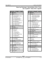
Y
Valve coil
Y2 = Brake release
Y3 = Steer right / CW
Y4 = Steer left / CCW
Y5 = Drive reverse
Y6 = Drive forward
Y7 = Platform down
Y7A = Platform down (GS-4069 models)
Y8 = Platform up
Y9 = Proportional flow control
Y10 = Auxiliary platform down
Y10A = Auxiliary platform down (GS-4069 models)
Y27 = 2 speed (high / low torque)
Y29 = Generator (option)
Y33 = Left rear outrigger (option)
Y34 = Right rear outrigger (option)
Y35 = Left front outrigger (option)
Y36 = Right front outrigger (option)
Y39 = Outrigger extend (option)
Y40 = Outrigger retract (option)
Y93 = Oscillate left
Y94 = Oscillate right
Y95 = Oscillate float
Y96 = Front motors isolate
Y97 = Front motors free wheel
Y98 = High speed bypass
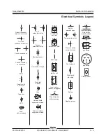
ELECTRICAL SCHEMATIC LEGEND
WIRE COLOR
LEGEND
Item
Description
BL
Blue
BK
Black
BR
Brown
GR
Green
OR
Orange
PP
Purple
RD
Red
WH
White
YL
Yellow
BL/RD
Blue/Red
BL/WH
Blue/White
BK/RD
Black/Red
OR/WH
Orange/White
RD/BK
Red/Black
RD/WH
Red/White
WH/BL
White Blue
WH/BK
White/Black
WH/RD
White/Red
WH/YL
White/Yellow
YL/BK
Yellow/Black
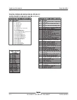
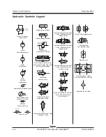
Item
Function
BA
3 position, 4 way directional valve - outrigger cylinders
extend/retract
DA
Proportional valve - controls flow to the generator
(option)
DB
Relief valve - reduces high pressure in the generator
(option)
FA
Flow regulator valve - controls flow to oscillate circuit
FB
2 position, 2 way valve- oscillate float
FC
Relief valve - oscillate circuit
FD
2 position, 3 way directional valve - platform up/down
FE
Relief valve - Platform up circuit
FF
Relief valve - Main system
FG
Differential sensing valve - meters flow to functions
FH
Check valve - differential sensing circuit
FI
Flow regulator valve - controls flow to the steer circuit
FJ
Check valve - steer circuit
FK
3 position, 5 way directional valve - steer right/left
FL
Proportional valve - controls function speeds
FM
Flow regulator valve - controls flow to lift and outriggers
FN
Pressure compensating valve - proportional valve
circuit
FO
2 position, 3 way valve - oscillate right
FP
2 position, 3 way valve - oscillate left
FQ
Sequence valve - oscillate float valve circuit
TA
2 position, 3 way valve - brake release
TB
2 position, 4 way valve - blocks flow to the steer motors
in high drive
TC
Bidirectional relief valve - drive circuit
TD
Needle valve - enables towing ability
TE
3 position, 4 way valve - drive forward/reverse
TF
Orifice - equalizes drive pressure at non-steer end
TG
Combiner/Divider valve - controls flow to front and rear
drive motors
TH
Combiner/Divider valve - Controls flow to steer end
drive motors
TI
Orifice - equalizes drive pressure at steer end
TJ
2 position, 2 way valve - high speed bypass
TK
2 position, 2 way - allows flow to loop the steer end
drive motors in high drive
TL
2 position, 3 way valve - two speed
TM
Orifice - brake circuit
TN
Orifice - two speed circuit
TO
Pressure reducing valve - two speed / brake circuit
TP
Orifice - equalizes drive pressure
TQ
Combiner/Divider valve - Controls flow to non-steer
end drive motors
TR
Counterbalance valve - Traction relief
TS
Check valve - two speed circuit
TT
Check valve - brake circuit
HYDRAULIC COMPONENT LEGEND
Содержание GS-2669 RT
Страница 168: ...Section 6 Schematics November2014 6 8 GS 2669 RT GS 3369 RT GS 4069 RT PartNo 229753 This page intentionally left blank ...
Страница 169: ...Section 6 Schematics November2014 6 9 Control Panel Circuit Diagram 6 10 ...
Страница 171: ...Section 6 Schematics November2014 6 11 Electrical Schematic GS 2669 RT and GS 3369 RT Gas LPG Models ANSI CSA 6 12 ...
Страница 174: ...November2014 Section 6 Schematics 6 14 6 13 Electrical Schematic GS 2669 RT and GS 3369 RT Gas LPG Models ANSI CSA ...
Страница 175: ...Section 6 Schematics November2014 6 15 Ground Control Box Layout GS 2669 RT and GS 3369 RT Gas LPG Models ANSI CSA 6 16 ...
Страница 179: ...Section 6 Schematics November2014 6 19 Electrical Schematic GS 2669 RT and GS 3369 RT Diesel Models ANSI CSA 6 20 ...
Страница 182: ...November2014 Section 6 Schematics 6 22 6 21 Electrical Schematic GS 2669 RT and GS 3369 RT Diesel Models ANSI CSA ...
Страница 183: ...Section 6 Schematics November2014 6 23 Ground Control Box Layout GS 2669 RT and GS 3369 RT Diesel Models ANSI CSA 6 24 ...
Страница 187: ...Section 6 Schematics November2014 6 27 6 28 Electrical Schematic GS 2669 RT and GS 3369 RT Gas LPG Models AS ...
Страница 190: ...November2014 Section 6 Schematics 6 30 6 29 Electrical Schematic GS 2669 RT and GS 3369 RT Gas LPG Models AS ...
Страница 191: ...Section 6 Schematics November2014 6 31 Ground Control Box Layout GS 2669 RT and GS 3369 RT Gas LPG Models AS 6 32 ...
Страница 194: ...November2014 Section 6 Schematics 6 34 6 33 Platform Control Box Layout GS 2669 RT and GS 3369 RT Gas LPG Models AS ...
Страница 195: ...Section 6 Schematics November2014 6 35 Electrical Schematic GS 2669 RT and GS 3369 RT Diesel Models AS 6 36 ...
Страница 198: ...November2014 Section 6 Schematics 6 38 6 37 Electrical Schematic GS 2669 RT and GS 3369 RT Diesel Models AS ...
Страница 199: ...Section 6 Schematics November2014 6 39 6 40 Ground Control Box Layout GS 2669 RT and GS 3369 RT Diesel Models AS ...
Страница 202: ...November2014 Section 6 Schematics 6 42 6 41 Platform Control Box Layout GS 2669 RT and GS 3369 RT Diesel Models AS ...
Страница 203: ...Section 6 Schematics November2014 6 43 Electrical Schematic GS 2669 RT and GS 3369 RT Gas LPG Models CE 6 44 ...
Страница 206: ...November2014 Section 6 Schematics 6 46 Electrical Schematic GS 2669 RT and GS 3369 RT Gas LPG Models CE 6 45 ...
Страница 207: ...Section 6 Schematics November2014 6 47 6 48 Ground Control Box Layout GS 2669 RT and GS 3369 RT Gas LPG Models CE ...
Страница 210: ...November2014 Section 6 Schematics 6 50 Platform Control Box Layout GS 2669 RT and GS 3369 RT Gas LPG Models CE 6 49 ...
Страница 211: ...Section 6 Schematics November2014 6 51 6 52 Electrical Schematic GS 2669 RT and GS 3369 RT Diesel Models CE ...
Страница 214: ...November2014 Section 6 Schematics 6 54 Electrical Schematic GS 2669 RT and GS 3369 RT Diesel Models CE 6 53 ...
Страница 215: ...Section 6 Schematics November2014 6 55 6 56 Ground Control Box Layout GS 2669 RT and GS 3369 RT Diesel Models CE ...
Страница 218: ...November2014 Section 6 Schematics 6 58 Platform Control Box Layout GS 2669 RT and GS 3369 RT Diesel Models CE 6 57 ...
Страница 219: ...Section 6 Schematics November2014 6 59 6 60 Electrical Schematic GS 4069 RT Gas LPG Models ANSI CSA ...
Страница 222: ...November2014 Section 6 Schematics 6 62 6 61 Electrical Schematic GS 4069 RT Gas LPG Models ANSI CSA ...
Страница 223: ...Section 6 Schematics November2014 6 63 6 64 Ground Control Box Layout GS 4069 RT Gas LPG Models ANSI CSA ...
Страница 226: ...November2014 Section 6 Schematics 6 66 6 65 Platform Control Box Layout GS 4069 RT Gas LPG Models ANSI CSA ...
Страница 227: ...Section 6 Schematics November2014 6 67 6 68 Electrical Schematic GS 4069 RT Diesel Models ANSI CSA ...
Страница 230: ...November2014 Section 6 Schematics 6 70 6 69 Electrical Schematic GS 4069 RT Diesel Models ANSI CSA ...
Страница 231: ...Section 6 Schematics November2014 6 71 6 72 Ground Control Box Layout GS 4069 RT Diesel Models ANSI CSA ...
Страница 234: ...November2014 Section 6 Schematics 6 74 6 73 Platform Control Box Layout GS 4069 RT Diesel Models ANSI CSA ...
Страница 235: ...Section 6 Schematics November2014 6 75 6 76 Electrical Schematic GS 4069 RT Gas LPG Models AS ...
Страница 238: ...November2014 Section 6 Schematics 6 78 Electrical Schematic GS 4069 RT Gas LPG Models AS 6 77 ...
Страница 239: ...Section 6 Schematics November2014 6 79 6 80 Ground Control Box Layout GS 4069 RT Gas LPG Models AS ...
Страница 242: ...November2014 Section 6 Schematics 6 82 Platform Control Box Layout GS 4069 RT Gas LPG Models AS 6 81 ...
Страница 243: ...Section 6 Schematics November2014 6 83 Electrical Schematic GS 4069 RT Diesel Models AS 6 82 ...
Страница 246: ...November2014 Section 6 Schematics 6 86 Electrical Schematic GS 4069 RT Diesel Models AS 6 85 ...
Страница 247: ...Section 6 Schematics November2014 6 87 6 88 Ground Control Box Layout GS 4069 RT Diesel Models AS ...
Страница 250: ...November2014 Section 6 Schematics 6 90 Platform Control Box Layout GS 4069 RT Diesel Models AS 6 89 ...
Страница 251: ...Section 6 Schematics November2014 6 91 Electrical Schematic GS 4069 RT Gas LPG Models CE 6 92 ...
Страница 254: ...November2014 Section 6 Schematics 6 94 Electrical Schematic GS 4069 RT Gas LPG Models CE 6 93 ...
Страница 255: ...Section 6 Schematics November2014 6 95 6 96 Ground Control Box Layout GS 4069 RT Gas LPG Models CE ...
Страница 258: ...November2014 Section 6 Schematics 6 98 Platform Control Box Layout GS 4069 RT Gas LPG Models CE 6 97 ...
Страница 259: ...Section 6 Schematics November2014 6 99 6 100 Electrical Schematic GS 4069 RT Diesel Models CE ...
Страница 262: ...November2014 Section 6 Schematics 6 102 Electrical Schematic GS 4069 RT Diesel Models CE 6 101 ...
Страница 263: ...Section 6 Schematics November2014 6 103 6 104 Ground Control Box Layout GS 4069 RT Diesel Models CE ...
Страница 266: ...November2014 Section 6 Schematics 6 106 Platform Control Box Layout GS 4069 RT Diesel Models CE 6 105 ...
Страница 267: ...Section 6 Schematics November2014 6 107 Hydraulic Schematic GS 2669 RT and GS 3369 RT 6 108 ...
Страница 270: ...November2014 Section 6 Schematics 6 110 Hydraulic Schematic GS 4069 RT 6 109 ...


