


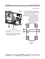


Section 4 • Repair Procedures
November 2014
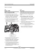
4 - 38
GS-2669 RT • GS-3369 RT • GS-4069 RT
Part No. 229753
b
c
d
a
7-3
Software Configuration
How to Configure the Software
The Electronic Control Module (ECM) contains
programming for all configurations of the GS-69.
Machines can be adjusted to a different
configuration using the buttons at the ground
controls. To determine the software revision level,
see 7-2,
How to Determine the Revision Level
.
ANSI and CSA models:
1 Turn the key switch to ground controls and pull
out the red Emergency Stop buttons to the on
position at both platform and ground controls.
Result: The revision level of the ECM will
appear in the LED display window. Note the
result.
2 Push in the red Emergency Stop button to the
off position at the ground controls.
3 Press and hold both the blue platform up and
yellow platform down buttons. Pull out the red
Emergency Stop button to the on position at the
ground controls.
Result:
TUNE
SPEEDS
is showing in the diagnostic
display window.
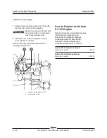
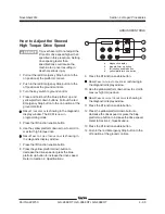
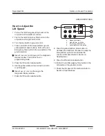
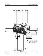
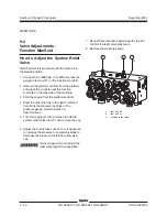
a
diagnostic display
b
blue platform up button
c
lift function enable button
d
yellow platform down button
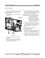
Machine Option Definitions
Descent Delay:
This option halts descent when
the down limit switch is activated. All controls
must be released for 4 to 6 seconds before
descent is re-enabled. Required for Europe.
Motion Alarm:
The motion alarm will sound
when activating a function.
Motion Beacons:
The flashing beacons
operate only when activating a function.
Overload:
This cuts out all functions when the
platform overload pressure switch is tripped.
The red Emergency Stop button must be
cycled before any function can be resumed.
Required for Europe and Australia.
Beacons:
When installed on the machine, the
flashing beacons operate continuously when
the key switch is turned to ground or platform
controls and both red Emergency Stop buttons
are pulled out to the on position.
Generator:
When installed on the machine, the
generator can only be operated when the
engine is running.
Sim Operation:
Not available.
Outriggers:
When installed on the machine,
the outrigger option must be enabled.
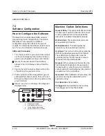
GROUND CONTROLS
Содержание GS-2669 RT
Страница 168: ...Section 6 Schematics November2014 6 8 GS 2669 RT GS 3369 RT GS 4069 RT PartNo 229753 This page intentionally left blank ...
Страница 169: ...Section 6 Schematics November2014 6 9 Control Panel Circuit Diagram 6 10 ...
Страница 171: ...Section 6 Schematics November2014 6 11 Electrical Schematic GS 2669 RT and GS 3369 RT Gas LPG Models ANSI CSA 6 12 ...
Страница 174: ...November2014 Section 6 Schematics 6 14 6 13 Electrical Schematic GS 2669 RT and GS 3369 RT Gas LPG Models ANSI CSA ...
Страница 175: ...Section 6 Schematics November2014 6 15 Ground Control Box Layout GS 2669 RT and GS 3369 RT Gas LPG Models ANSI CSA 6 16 ...
Страница 179: ...Section 6 Schematics November2014 6 19 Electrical Schematic GS 2669 RT and GS 3369 RT Diesel Models ANSI CSA 6 20 ...
Страница 182: ...November2014 Section 6 Schematics 6 22 6 21 Electrical Schematic GS 2669 RT and GS 3369 RT Diesel Models ANSI CSA ...
Страница 183: ...Section 6 Schematics November2014 6 23 Ground Control Box Layout GS 2669 RT and GS 3369 RT Diesel Models ANSI CSA 6 24 ...
Страница 187: ...Section 6 Schematics November2014 6 27 6 28 Electrical Schematic GS 2669 RT and GS 3369 RT Gas LPG Models AS ...
Страница 190: ...November2014 Section 6 Schematics 6 30 6 29 Electrical Schematic GS 2669 RT and GS 3369 RT Gas LPG Models AS ...
Страница 191: ...Section 6 Schematics November2014 6 31 Ground Control Box Layout GS 2669 RT and GS 3369 RT Gas LPG Models AS 6 32 ...
Страница 194: ...November2014 Section 6 Schematics 6 34 6 33 Platform Control Box Layout GS 2669 RT and GS 3369 RT Gas LPG Models AS ...
Страница 195: ...Section 6 Schematics November2014 6 35 Electrical Schematic GS 2669 RT and GS 3369 RT Diesel Models AS 6 36 ...
Страница 198: ...November2014 Section 6 Schematics 6 38 6 37 Electrical Schematic GS 2669 RT and GS 3369 RT Diesel Models AS ...
Страница 199: ...Section 6 Schematics November2014 6 39 6 40 Ground Control Box Layout GS 2669 RT and GS 3369 RT Diesel Models AS ...
Страница 202: ...November2014 Section 6 Schematics 6 42 6 41 Platform Control Box Layout GS 2669 RT and GS 3369 RT Diesel Models AS ...
Страница 203: ...Section 6 Schematics November2014 6 43 Electrical Schematic GS 2669 RT and GS 3369 RT Gas LPG Models CE 6 44 ...
Страница 206: ...November2014 Section 6 Schematics 6 46 Electrical Schematic GS 2669 RT and GS 3369 RT Gas LPG Models CE 6 45 ...
Страница 207: ...Section 6 Schematics November2014 6 47 6 48 Ground Control Box Layout GS 2669 RT and GS 3369 RT Gas LPG Models CE ...
Страница 210: ...November2014 Section 6 Schematics 6 50 Platform Control Box Layout GS 2669 RT and GS 3369 RT Gas LPG Models CE 6 49 ...
Страница 211: ...Section 6 Schematics November2014 6 51 6 52 Electrical Schematic GS 2669 RT and GS 3369 RT Diesel Models CE ...
Страница 214: ...November2014 Section 6 Schematics 6 54 Electrical Schematic GS 2669 RT and GS 3369 RT Diesel Models CE 6 53 ...
Страница 215: ...Section 6 Schematics November2014 6 55 6 56 Ground Control Box Layout GS 2669 RT and GS 3369 RT Diesel Models CE ...
Страница 218: ...November2014 Section 6 Schematics 6 58 Platform Control Box Layout GS 2669 RT and GS 3369 RT Diesel Models CE 6 57 ...
Страница 219: ...Section 6 Schematics November2014 6 59 6 60 Electrical Schematic GS 4069 RT Gas LPG Models ANSI CSA ...
Страница 222: ...November2014 Section 6 Schematics 6 62 6 61 Electrical Schematic GS 4069 RT Gas LPG Models ANSI CSA ...
Страница 223: ...Section 6 Schematics November2014 6 63 6 64 Ground Control Box Layout GS 4069 RT Gas LPG Models ANSI CSA ...
Страница 226: ...November2014 Section 6 Schematics 6 66 6 65 Platform Control Box Layout GS 4069 RT Gas LPG Models ANSI CSA ...
Страница 227: ...Section 6 Schematics November2014 6 67 6 68 Electrical Schematic GS 4069 RT Diesel Models ANSI CSA ...
Страница 230: ...November2014 Section 6 Schematics 6 70 6 69 Electrical Schematic GS 4069 RT Diesel Models ANSI CSA ...
Страница 231: ...Section 6 Schematics November2014 6 71 6 72 Ground Control Box Layout GS 4069 RT Diesel Models ANSI CSA ...
Страница 234: ...November2014 Section 6 Schematics 6 74 6 73 Platform Control Box Layout GS 4069 RT Diesel Models ANSI CSA ...
Страница 235: ...Section 6 Schematics November2014 6 75 6 76 Electrical Schematic GS 4069 RT Gas LPG Models AS ...
Страница 238: ...November2014 Section 6 Schematics 6 78 Electrical Schematic GS 4069 RT Gas LPG Models AS 6 77 ...
Страница 239: ...Section 6 Schematics November2014 6 79 6 80 Ground Control Box Layout GS 4069 RT Gas LPG Models AS ...
Страница 242: ...November2014 Section 6 Schematics 6 82 Platform Control Box Layout GS 4069 RT Gas LPG Models AS 6 81 ...
Страница 243: ...Section 6 Schematics November2014 6 83 Electrical Schematic GS 4069 RT Diesel Models AS 6 82 ...
Страница 246: ...November2014 Section 6 Schematics 6 86 Electrical Schematic GS 4069 RT Diesel Models AS 6 85 ...
Страница 247: ...Section 6 Schematics November2014 6 87 6 88 Ground Control Box Layout GS 4069 RT Diesel Models AS ...
Страница 250: ...November2014 Section 6 Schematics 6 90 Platform Control Box Layout GS 4069 RT Diesel Models AS 6 89 ...
Страница 251: ...Section 6 Schematics November2014 6 91 Electrical Schematic GS 4069 RT Gas LPG Models CE 6 92 ...
Страница 254: ...November2014 Section 6 Schematics 6 94 Electrical Schematic GS 4069 RT Gas LPG Models CE 6 93 ...
Страница 255: ...Section 6 Schematics November2014 6 95 6 96 Ground Control Box Layout GS 4069 RT Gas LPG Models CE ...
Страница 258: ...November2014 Section 6 Schematics 6 98 Platform Control Box Layout GS 4069 RT Gas LPG Models CE 6 97 ...
Страница 259: ...Section 6 Schematics November2014 6 99 6 100 Electrical Schematic GS 4069 RT Diesel Models CE ...
Страница 262: ...November2014 Section 6 Schematics 6 102 Electrical Schematic GS 4069 RT Diesel Models CE 6 101 ...
Страница 263: ...Section 6 Schematics November2014 6 103 6 104 Ground Control Box Layout GS 4069 RT Diesel Models CE ...
Страница 266: ...November2014 Section 6 Schematics 6 106 Platform Control Box Layout GS 4069 RT Diesel Models CE 6 105 ...
Страница 267: ...Section 6 Schematics November2014 6 107 Hydraulic Schematic GS 2669 RT and GS 3369 RT 6 108 ...
Страница 270: ...November2014 Section 6 Schematics 6 110 Hydraulic Schematic GS 4069 RT 6 109 ...


