
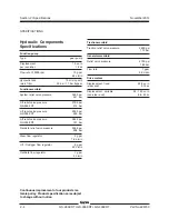


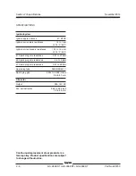
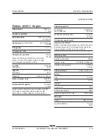


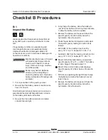


Section 3 • Scheduled Maintenance Procedures
November 2014
Part No. 229753
GS-2669 RT • GS-3369 RT • GS-4069 RT
3 - 5
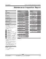
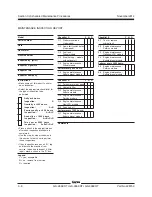
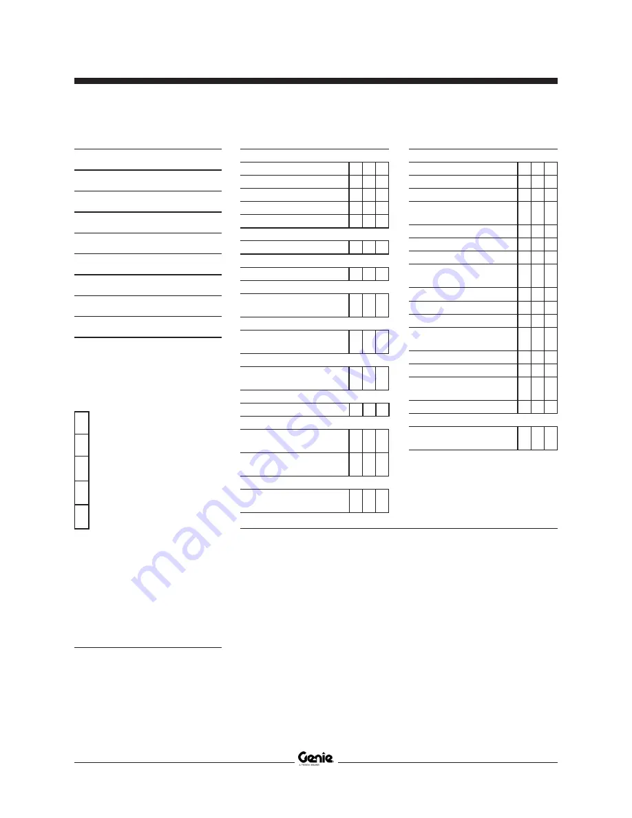
Maintenance Inspection Report
Checklist A
Y N R
A-1 Manuals and decals
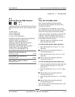
A-2 Pre-operation inspect
A-3 Function tests
A-4 Engine maintenance
A-5 Test the oscillate
Perform every 40 hours:
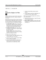
A-6 Engine air filter
Perform after 40 hours:
A-7 30 day service
Perform after 50 hours:
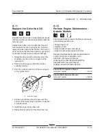
A-8 Engine maintenance -
Kubota models
Perform every 50 hours:
A-9 Engine maintenance -
Kubota models
Perform every 100 hours:
A-10 Engine maintenance -
Kubota models
Perform every 150 hours:
A-11 Drive hub oil
Perform every 200 hours:
A-12 Engine maintenance -
Kubota models
A-13 Drain filter/separator -
Kubota diesel models
Perform every 1-2 months:
A-14 Engine maintenance -
Kubota diesel models
Model
Serial number
Date
Hour meter
Machine owner
Inspected by (print)
Inspector signature
Inspector title
Inspector company
Instructions
• Make copies of this report to use for
each inspection.
• Select the appropriate checklist(s) for
the type of inspection to be
performed.
Daily or 8 hours
Inspection:
A
Quarterly or 250 hours
Inspection:
A+B
Semiannually or 500 hours
Inspection:
A+B+C
Annually or 1000 hours
Inspection:
A+B+C+D
Two year or 2000 hours
Inspection:
A+B+C+D+E
• Place a check in the appropriate box
after each inspection procedure is
completed.
• Use the step-by-step procedures in
this section to learn how to perform
these inspections.
• If any inspection receives an “N”, tag
and remove the machine from
service, repair and reinspect it. After
repair, place a check in the “R” box.
Legend
Y = yes, acceptable
N = no, remove from service
R = repaired
Comments
Checklist B
Y N R
B-1 Battery
B-2 Electrical wiring
B-3 Tires and wheels
B-4 Engine maintenance -
Perkins models
B-5 Key switch
B-6 Emergency Stop
B-7 Horn
B-8 Fuel select -
Gasoline/LPG models
B-9 Drive brakes
B-10 Drive speed - stowed
B-11 Drive speed - raised
B-12 Fuel tank check valve -
Gas / LPG Models
B-13 Tank venting systems
B-14 Hydraulic oil analysis
B-15 Flashing beacons
(if equipped)
B-16 Drive hub oil
Perform every 400 hours:
B-17 Engine maintenance -
Kubota diesel models
Содержание GS-2669 RT
Страница 168: ...Section 6 Schematics November2014 6 8 GS 2669 RT GS 3369 RT GS 4069 RT PartNo 229753 This page intentionally left blank ...
Страница 169: ...Section 6 Schematics November2014 6 9 Control Panel Circuit Diagram 6 10 ...
Страница 171: ...Section 6 Schematics November2014 6 11 Electrical Schematic GS 2669 RT and GS 3369 RT Gas LPG Models ANSI CSA 6 12 ...
Страница 174: ...November2014 Section 6 Schematics 6 14 6 13 Electrical Schematic GS 2669 RT and GS 3369 RT Gas LPG Models ANSI CSA ...
Страница 175: ...Section 6 Schematics November2014 6 15 Ground Control Box Layout GS 2669 RT and GS 3369 RT Gas LPG Models ANSI CSA 6 16 ...
Страница 179: ...Section 6 Schematics November2014 6 19 Electrical Schematic GS 2669 RT and GS 3369 RT Diesel Models ANSI CSA 6 20 ...
Страница 182: ...November2014 Section 6 Schematics 6 22 6 21 Electrical Schematic GS 2669 RT and GS 3369 RT Diesel Models ANSI CSA ...
Страница 183: ...Section 6 Schematics November2014 6 23 Ground Control Box Layout GS 2669 RT and GS 3369 RT Diesel Models ANSI CSA 6 24 ...
Страница 187: ...Section 6 Schematics November2014 6 27 6 28 Electrical Schematic GS 2669 RT and GS 3369 RT Gas LPG Models AS ...
Страница 190: ...November2014 Section 6 Schematics 6 30 6 29 Electrical Schematic GS 2669 RT and GS 3369 RT Gas LPG Models AS ...
Страница 191: ...Section 6 Schematics November2014 6 31 Ground Control Box Layout GS 2669 RT and GS 3369 RT Gas LPG Models AS 6 32 ...
Страница 194: ...November2014 Section 6 Schematics 6 34 6 33 Platform Control Box Layout GS 2669 RT and GS 3369 RT Gas LPG Models AS ...
Страница 195: ...Section 6 Schematics November2014 6 35 Electrical Schematic GS 2669 RT and GS 3369 RT Diesel Models AS 6 36 ...
Страница 198: ...November2014 Section 6 Schematics 6 38 6 37 Electrical Schematic GS 2669 RT and GS 3369 RT Diesel Models AS ...
Страница 199: ...Section 6 Schematics November2014 6 39 6 40 Ground Control Box Layout GS 2669 RT and GS 3369 RT Diesel Models AS ...
Страница 202: ...November2014 Section 6 Schematics 6 42 6 41 Platform Control Box Layout GS 2669 RT and GS 3369 RT Diesel Models AS ...
Страница 203: ...Section 6 Schematics November2014 6 43 Electrical Schematic GS 2669 RT and GS 3369 RT Gas LPG Models CE 6 44 ...
Страница 206: ...November2014 Section 6 Schematics 6 46 Electrical Schematic GS 2669 RT and GS 3369 RT Gas LPG Models CE 6 45 ...
Страница 207: ...Section 6 Schematics November2014 6 47 6 48 Ground Control Box Layout GS 2669 RT and GS 3369 RT Gas LPG Models CE ...
Страница 210: ...November2014 Section 6 Schematics 6 50 Platform Control Box Layout GS 2669 RT and GS 3369 RT Gas LPG Models CE 6 49 ...
Страница 211: ...Section 6 Schematics November2014 6 51 6 52 Electrical Schematic GS 2669 RT and GS 3369 RT Diesel Models CE ...
Страница 214: ...November2014 Section 6 Schematics 6 54 Electrical Schematic GS 2669 RT and GS 3369 RT Diesel Models CE 6 53 ...
Страница 215: ...Section 6 Schematics November2014 6 55 6 56 Ground Control Box Layout GS 2669 RT and GS 3369 RT Diesel Models CE ...
Страница 218: ...November2014 Section 6 Schematics 6 58 Platform Control Box Layout GS 2669 RT and GS 3369 RT Diesel Models CE 6 57 ...
Страница 219: ...Section 6 Schematics November2014 6 59 6 60 Electrical Schematic GS 4069 RT Gas LPG Models ANSI CSA ...
Страница 222: ...November2014 Section 6 Schematics 6 62 6 61 Electrical Schematic GS 4069 RT Gas LPG Models ANSI CSA ...
Страница 223: ...Section 6 Schematics November2014 6 63 6 64 Ground Control Box Layout GS 4069 RT Gas LPG Models ANSI CSA ...
Страница 226: ...November2014 Section 6 Schematics 6 66 6 65 Platform Control Box Layout GS 4069 RT Gas LPG Models ANSI CSA ...
Страница 227: ...Section 6 Schematics November2014 6 67 6 68 Electrical Schematic GS 4069 RT Diesel Models ANSI CSA ...
Страница 230: ...November2014 Section 6 Schematics 6 70 6 69 Electrical Schematic GS 4069 RT Diesel Models ANSI CSA ...
Страница 231: ...Section 6 Schematics November2014 6 71 6 72 Ground Control Box Layout GS 4069 RT Diesel Models ANSI CSA ...
Страница 234: ...November2014 Section 6 Schematics 6 74 6 73 Platform Control Box Layout GS 4069 RT Diesel Models ANSI CSA ...
Страница 235: ...Section 6 Schematics November2014 6 75 6 76 Electrical Schematic GS 4069 RT Gas LPG Models AS ...
Страница 238: ...November2014 Section 6 Schematics 6 78 Electrical Schematic GS 4069 RT Gas LPG Models AS 6 77 ...
Страница 239: ...Section 6 Schematics November2014 6 79 6 80 Ground Control Box Layout GS 4069 RT Gas LPG Models AS ...
Страница 242: ...November2014 Section 6 Schematics 6 82 Platform Control Box Layout GS 4069 RT Gas LPG Models AS 6 81 ...
Страница 243: ...Section 6 Schematics November2014 6 83 Electrical Schematic GS 4069 RT Diesel Models AS 6 82 ...
Страница 246: ...November2014 Section 6 Schematics 6 86 Electrical Schematic GS 4069 RT Diesel Models AS 6 85 ...
Страница 247: ...Section 6 Schematics November2014 6 87 6 88 Ground Control Box Layout GS 4069 RT Diesel Models AS ...
Страница 250: ...November2014 Section 6 Schematics 6 90 Platform Control Box Layout GS 4069 RT Diesel Models AS 6 89 ...
Страница 251: ...Section 6 Schematics November2014 6 91 Electrical Schematic GS 4069 RT Gas LPG Models CE 6 92 ...
Страница 254: ...November2014 Section 6 Schematics 6 94 Electrical Schematic GS 4069 RT Gas LPG Models CE 6 93 ...
Страница 255: ...Section 6 Schematics November2014 6 95 6 96 Ground Control Box Layout GS 4069 RT Gas LPG Models CE ...
Страница 258: ...November2014 Section 6 Schematics 6 98 Platform Control Box Layout GS 4069 RT Gas LPG Models CE 6 97 ...
Страница 259: ...Section 6 Schematics November2014 6 99 6 100 Electrical Schematic GS 4069 RT Diesel Models CE ...
Страница 262: ...November2014 Section 6 Schematics 6 102 Electrical Schematic GS 4069 RT Diesel Models CE 6 101 ...
Страница 263: ...Section 6 Schematics November2014 6 103 6 104 Ground Control Box Layout GS 4069 RT Diesel Models CE ...
Страница 266: ...November2014 Section 6 Schematics 6 106 Platform Control Box Layout GS 4069 RT Diesel Models CE 6 105 ...
Страница 267: ...Section 6 Schematics November2014 6 107 Hydraulic Schematic GS 2669 RT and GS 3369 RT 6 108 ...
Страница 270: ...November2014 Section 6 Schematics 6 110 Hydraulic Schematic GS 4069 RT 6 109 ...


