


Section 4 • Repair Procedures
November 2014
Part No. 229753
GS-2669 RT • GS-3369 RT • GS-4069 RT
4 - 43
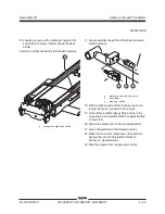
24 Lower the platform to the stowed position.
25 Push in the red Emergency Stop button to the
off position at both the ground and platform
controls.
26 Turn the key switch to the off position.
27 Raise the machine approximately
4 inches / 10 cm.
28 Remove the blocks from under both wheels.
29 Lower the machine and remove the jack.
7-5
Level Sensor -
Models with Outriggers
The Electronic Control Module (ECM) is
programmed to deactivate the lift and drive
functions and activate an alarm when a signal is
received from the level sensor.
When the outriggers are stowed, the tilt alarm
sounds when the incline of the chassis exceeds 2°
to the side.
When the outriggers are deployed, the tilt alarm
sounds when the incline of the chassis exceeds
0.8° to the side.
At all times, the tilt alarm sounds when the incline
of the chassis exceeds 3° to the front or rear.
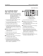
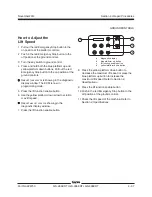
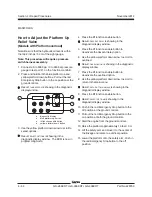
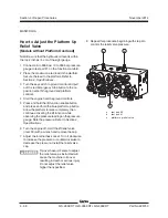
How to Install and Calibrate the
Level Sensor
Tip-over hazard. Failure to install
or calibrate the level sensor as
instructed could result in the
machine tipping over causing
death or serious injury. Do not
install or calibrate the level sensor
other than specified in this
procedure.
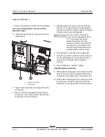
Note: Perform this procedure with the machine on a
firm, level surface and the platform in the stowed
position. Use a digital level to confirm.
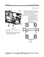
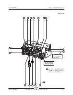
GROUND CONTROLS
Содержание GS-2669 RT
Страница 168: ...Section 6 Schematics November2014 6 8 GS 2669 RT GS 3369 RT GS 4069 RT PartNo 229753 This page intentionally left blank ...
Страница 169: ...Section 6 Schematics November2014 6 9 Control Panel Circuit Diagram 6 10 ...
Страница 171: ...Section 6 Schematics November2014 6 11 Electrical Schematic GS 2669 RT and GS 3369 RT Gas LPG Models ANSI CSA 6 12 ...
Страница 174: ...November2014 Section 6 Schematics 6 14 6 13 Electrical Schematic GS 2669 RT and GS 3369 RT Gas LPG Models ANSI CSA ...
Страница 175: ...Section 6 Schematics November2014 6 15 Ground Control Box Layout GS 2669 RT and GS 3369 RT Gas LPG Models ANSI CSA 6 16 ...
Страница 179: ...Section 6 Schematics November2014 6 19 Electrical Schematic GS 2669 RT and GS 3369 RT Diesel Models ANSI CSA 6 20 ...
Страница 182: ...November2014 Section 6 Schematics 6 22 6 21 Electrical Schematic GS 2669 RT and GS 3369 RT Diesel Models ANSI CSA ...
Страница 183: ...Section 6 Schematics November2014 6 23 Ground Control Box Layout GS 2669 RT and GS 3369 RT Diesel Models ANSI CSA 6 24 ...
Страница 187: ...Section 6 Schematics November2014 6 27 6 28 Electrical Schematic GS 2669 RT and GS 3369 RT Gas LPG Models AS ...
Страница 190: ...November2014 Section 6 Schematics 6 30 6 29 Electrical Schematic GS 2669 RT and GS 3369 RT Gas LPG Models AS ...
Страница 191: ...Section 6 Schematics November2014 6 31 Ground Control Box Layout GS 2669 RT and GS 3369 RT Gas LPG Models AS 6 32 ...
Страница 194: ...November2014 Section 6 Schematics 6 34 6 33 Platform Control Box Layout GS 2669 RT and GS 3369 RT Gas LPG Models AS ...
Страница 195: ...Section 6 Schematics November2014 6 35 Electrical Schematic GS 2669 RT and GS 3369 RT Diesel Models AS 6 36 ...
Страница 198: ...November2014 Section 6 Schematics 6 38 6 37 Electrical Schematic GS 2669 RT and GS 3369 RT Diesel Models AS ...
Страница 199: ...Section 6 Schematics November2014 6 39 6 40 Ground Control Box Layout GS 2669 RT and GS 3369 RT Diesel Models AS ...
Страница 202: ...November2014 Section 6 Schematics 6 42 6 41 Platform Control Box Layout GS 2669 RT and GS 3369 RT Diesel Models AS ...
Страница 203: ...Section 6 Schematics November2014 6 43 Electrical Schematic GS 2669 RT and GS 3369 RT Gas LPG Models CE 6 44 ...
Страница 206: ...November2014 Section 6 Schematics 6 46 Electrical Schematic GS 2669 RT and GS 3369 RT Gas LPG Models CE 6 45 ...
Страница 207: ...Section 6 Schematics November2014 6 47 6 48 Ground Control Box Layout GS 2669 RT and GS 3369 RT Gas LPG Models CE ...
Страница 210: ...November2014 Section 6 Schematics 6 50 Platform Control Box Layout GS 2669 RT and GS 3369 RT Gas LPG Models CE 6 49 ...
Страница 211: ...Section 6 Schematics November2014 6 51 6 52 Electrical Schematic GS 2669 RT and GS 3369 RT Diesel Models CE ...
Страница 214: ...November2014 Section 6 Schematics 6 54 Electrical Schematic GS 2669 RT and GS 3369 RT Diesel Models CE 6 53 ...
Страница 215: ...Section 6 Schematics November2014 6 55 6 56 Ground Control Box Layout GS 2669 RT and GS 3369 RT Diesel Models CE ...
Страница 218: ...November2014 Section 6 Schematics 6 58 Platform Control Box Layout GS 2669 RT and GS 3369 RT Diesel Models CE 6 57 ...
Страница 219: ...Section 6 Schematics November2014 6 59 6 60 Electrical Schematic GS 4069 RT Gas LPG Models ANSI CSA ...
Страница 222: ...November2014 Section 6 Schematics 6 62 6 61 Electrical Schematic GS 4069 RT Gas LPG Models ANSI CSA ...
Страница 223: ...Section 6 Schematics November2014 6 63 6 64 Ground Control Box Layout GS 4069 RT Gas LPG Models ANSI CSA ...
Страница 226: ...November2014 Section 6 Schematics 6 66 6 65 Platform Control Box Layout GS 4069 RT Gas LPG Models ANSI CSA ...
Страница 227: ...Section 6 Schematics November2014 6 67 6 68 Electrical Schematic GS 4069 RT Diesel Models ANSI CSA ...
Страница 230: ...November2014 Section 6 Schematics 6 70 6 69 Electrical Schematic GS 4069 RT Diesel Models ANSI CSA ...
Страница 231: ...Section 6 Schematics November2014 6 71 6 72 Ground Control Box Layout GS 4069 RT Diesel Models ANSI CSA ...
Страница 234: ...November2014 Section 6 Schematics 6 74 6 73 Platform Control Box Layout GS 4069 RT Diesel Models ANSI CSA ...
Страница 235: ...Section 6 Schematics November2014 6 75 6 76 Electrical Schematic GS 4069 RT Gas LPG Models AS ...
Страница 238: ...November2014 Section 6 Schematics 6 78 Electrical Schematic GS 4069 RT Gas LPG Models AS 6 77 ...
Страница 239: ...Section 6 Schematics November2014 6 79 6 80 Ground Control Box Layout GS 4069 RT Gas LPG Models AS ...
Страница 242: ...November2014 Section 6 Schematics 6 82 Platform Control Box Layout GS 4069 RT Gas LPG Models AS 6 81 ...
Страница 243: ...Section 6 Schematics November2014 6 83 Electrical Schematic GS 4069 RT Diesel Models AS 6 82 ...
Страница 246: ...November2014 Section 6 Schematics 6 86 Electrical Schematic GS 4069 RT Diesel Models AS 6 85 ...
Страница 247: ...Section 6 Schematics November2014 6 87 6 88 Ground Control Box Layout GS 4069 RT Diesel Models AS ...
Страница 250: ...November2014 Section 6 Schematics 6 90 Platform Control Box Layout GS 4069 RT Diesel Models AS 6 89 ...
Страница 251: ...Section 6 Schematics November2014 6 91 Electrical Schematic GS 4069 RT Gas LPG Models CE 6 92 ...
Страница 254: ...November2014 Section 6 Schematics 6 94 Electrical Schematic GS 4069 RT Gas LPG Models CE 6 93 ...
Страница 255: ...Section 6 Schematics November2014 6 95 6 96 Ground Control Box Layout GS 4069 RT Gas LPG Models CE ...
Страница 258: ...November2014 Section 6 Schematics 6 98 Platform Control Box Layout GS 4069 RT Gas LPG Models CE 6 97 ...
Страница 259: ...Section 6 Schematics November2014 6 99 6 100 Electrical Schematic GS 4069 RT Diesel Models CE ...
Страница 262: ...November2014 Section 6 Schematics 6 102 Electrical Schematic GS 4069 RT Diesel Models CE 6 101 ...
Страница 263: ...Section 6 Schematics November2014 6 103 6 104 Ground Control Box Layout GS 4069 RT Diesel Models CE ...
Страница 266: ...November2014 Section 6 Schematics 6 106 Platform Control Box Layout GS 4069 RT Diesel Models CE 6 105 ...
Страница 267: ...Section 6 Schematics November2014 6 107 Hydraulic Schematic GS 2669 RT and GS 3369 RT 6 108 ...
Страница 270: ...November2014 Section 6 Schematics 6 110 Hydraulic Schematic GS 4069 RT 6 109 ...


