


Section 3 • Scheduled Maintenance Procedures
November 2014
Part No. 229753
GS-2669 RT • GS-3369 RT • GS-4069 RT
3 - 1
Scheduled Maintenance Procedures
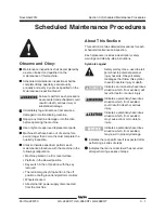
Observe and Obey:
Maintenance inspections shall be completed by
a person trained and qualified on the
maintenance of this machine.
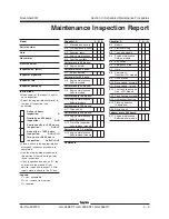
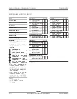
Scheduled maintenance inspections shall be
completed daily, quarterly, semiannually,
annually and every 2 years as specified on the
Maintenance Inspection Report.
Failure to perform each procedure
as presented and scheduled could
result in death, serious injury or
substantial damage.
Immediately tag and remove from service a
damaged or malfunctioning machine.
Repair any machine damage or malfunction
before operating the machine.
Use only Genie approved replacement parts.
Machines that have been out of service for a
period longer than 3 months must complete the
quarterly inspection.
Unless otherwise specified, perform each
maintenance procedure with the machine in the
following configuration:
• Machine parked on a firm, level surface
• Platform in the stowed position
• Key switch in the off position with the key
removed
• The red Emergency Stop button in the off
position at both ground and platform controls
• Wheels chocked
• All external AC power supply disconnected
from the machine
About This Section
This section contains detailed procedures for each
scheduled maintenance inspection.
Each procedure includes a description, safety
warnings and step-by-step instructions.
Symbols Legend
Safety alert symbol—used to alert
personnel to potential personal
injury hazards. Obey all safety
messages that follow this symbol
to avoid possible injury or death.
Indicates an imminently hazardous
situation which, if not avoided, will
result in death or serious injury.
Indicates a potentially hazardous
situation which, if not avoided,
could result in death or serious
injury.
Indicates a potentially hazardous
situation which, if not avoided,
may cause minor or moderate
injury.
Indicates a potentially hazardous
situation which, if not avoided,
may result in property damage.
Indicates that a specific result is expected after
performing a series of steps.
Indicates that an incorrect result has occurred
after performing a series of steps.
Содержание GS-2669 RT
Страница 168: ...Section 6 Schematics November2014 6 8 GS 2669 RT GS 3369 RT GS 4069 RT PartNo 229753 This page intentionally left blank ...
Страница 169: ...Section 6 Schematics November2014 6 9 Control Panel Circuit Diagram 6 10 ...
Страница 171: ...Section 6 Schematics November2014 6 11 Electrical Schematic GS 2669 RT and GS 3369 RT Gas LPG Models ANSI CSA 6 12 ...
Страница 174: ...November2014 Section 6 Schematics 6 14 6 13 Electrical Schematic GS 2669 RT and GS 3369 RT Gas LPG Models ANSI CSA ...
Страница 175: ...Section 6 Schematics November2014 6 15 Ground Control Box Layout GS 2669 RT and GS 3369 RT Gas LPG Models ANSI CSA 6 16 ...
Страница 179: ...Section 6 Schematics November2014 6 19 Electrical Schematic GS 2669 RT and GS 3369 RT Diesel Models ANSI CSA 6 20 ...
Страница 182: ...November2014 Section 6 Schematics 6 22 6 21 Electrical Schematic GS 2669 RT and GS 3369 RT Diesel Models ANSI CSA ...
Страница 183: ...Section 6 Schematics November2014 6 23 Ground Control Box Layout GS 2669 RT and GS 3369 RT Diesel Models ANSI CSA 6 24 ...
Страница 187: ...Section 6 Schematics November2014 6 27 6 28 Electrical Schematic GS 2669 RT and GS 3369 RT Gas LPG Models AS ...
Страница 190: ...November2014 Section 6 Schematics 6 30 6 29 Electrical Schematic GS 2669 RT and GS 3369 RT Gas LPG Models AS ...
Страница 191: ...Section 6 Schematics November2014 6 31 Ground Control Box Layout GS 2669 RT and GS 3369 RT Gas LPG Models AS 6 32 ...
Страница 194: ...November2014 Section 6 Schematics 6 34 6 33 Platform Control Box Layout GS 2669 RT and GS 3369 RT Gas LPG Models AS ...
Страница 195: ...Section 6 Schematics November2014 6 35 Electrical Schematic GS 2669 RT and GS 3369 RT Diesel Models AS 6 36 ...
Страница 198: ...November2014 Section 6 Schematics 6 38 6 37 Electrical Schematic GS 2669 RT and GS 3369 RT Diesel Models AS ...
Страница 199: ...Section 6 Schematics November2014 6 39 6 40 Ground Control Box Layout GS 2669 RT and GS 3369 RT Diesel Models AS ...
Страница 202: ...November2014 Section 6 Schematics 6 42 6 41 Platform Control Box Layout GS 2669 RT and GS 3369 RT Diesel Models AS ...
Страница 203: ...Section 6 Schematics November2014 6 43 Electrical Schematic GS 2669 RT and GS 3369 RT Gas LPG Models CE 6 44 ...
Страница 206: ...November2014 Section 6 Schematics 6 46 Electrical Schematic GS 2669 RT and GS 3369 RT Gas LPG Models CE 6 45 ...
Страница 207: ...Section 6 Schematics November2014 6 47 6 48 Ground Control Box Layout GS 2669 RT and GS 3369 RT Gas LPG Models CE ...
Страница 210: ...November2014 Section 6 Schematics 6 50 Platform Control Box Layout GS 2669 RT and GS 3369 RT Gas LPG Models CE 6 49 ...
Страница 211: ...Section 6 Schematics November2014 6 51 6 52 Electrical Schematic GS 2669 RT and GS 3369 RT Diesel Models CE ...
Страница 214: ...November2014 Section 6 Schematics 6 54 Electrical Schematic GS 2669 RT and GS 3369 RT Diesel Models CE 6 53 ...
Страница 215: ...Section 6 Schematics November2014 6 55 6 56 Ground Control Box Layout GS 2669 RT and GS 3369 RT Diesel Models CE ...
Страница 218: ...November2014 Section 6 Schematics 6 58 Platform Control Box Layout GS 2669 RT and GS 3369 RT Diesel Models CE 6 57 ...
Страница 219: ...Section 6 Schematics November2014 6 59 6 60 Electrical Schematic GS 4069 RT Gas LPG Models ANSI CSA ...
Страница 222: ...November2014 Section 6 Schematics 6 62 6 61 Electrical Schematic GS 4069 RT Gas LPG Models ANSI CSA ...
Страница 223: ...Section 6 Schematics November2014 6 63 6 64 Ground Control Box Layout GS 4069 RT Gas LPG Models ANSI CSA ...
Страница 226: ...November2014 Section 6 Schematics 6 66 6 65 Platform Control Box Layout GS 4069 RT Gas LPG Models ANSI CSA ...
Страница 227: ...Section 6 Schematics November2014 6 67 6 68 Electrical Schematic GS 4069 RT Diesel Models ANSI CSA ...
Страница 230: ...November2014 Section 6 Schematics 6 70 6 69 Electrical Schematic GS 4069 RT Diesel Models ANSI CSA ...
Страница 231: ...Section 6 Schematics November2014 6 71 6 72 Ground Control Box Layout GS 4069 RT Diesel Models ANSI CSA ...
Страница 234: ...November2014 Section 6 Schematics 6 74 6 73 Platform Control Box Layout GS 4069 RT Diesel Models ANSI CSA ...
Страница 235: ...Section 6 Schematics November2014 6 75 6 76 Electrical Schematic GS 4069 RT Gas LPG Models AS ...
Страница 238: ...November2014 Section 6 Schematics 6 78 Electrical Schematic GS 4069 RT Gas LPG Models AS 6 77 ...
Страница 239: ...Section 6 Schematics November2014 6 79 6 80 Ground Control Box Layout GS 4069 RT Gas LPG Models AS ...
Страница 242: ...November2014 Section 6 Schematics 6 82 Platform Control Box Layout GS 4069 RT Gas LPG Models AS 6 81 ...
Страница 243: ...Section 6 Schematics November2014 6 83 Electrical Schematic GS 4069 RT Diesel Models AS 6 82 ...
Страница 246: ...November2014 Section 6 Schematics 6 86 Electrical Schematic GS 4069 RT Diesel Models AS 6 85 ...
Страница 247: ...Section 6 Schematics November2014 6 87 6 88 Ground Control Box Layout GS 4069 RT Diesel Models AS ...
Страница 250: ...November2014 Section 6 Schematics 6 90 Platform Control Box Layout GS 4069 RT Diesel Models AS 6 89 ...
Страница 251: ...Section 6 Schematics November2014 6 91 Electrical Schematic GS 4069 RT Gas LPG Models CE 6 92 ...
Страница 254: ...November2014 Section 6 Schematics 6 94 Electrical Schematic GS 4069 RT Gas LPG Models CE 6 93 ...
Страница 255: ...Section 6 Schematics November2014 6 95 6 96 Ground Control Box Layout GS 4069 RT Gas LPG Models CE ...
Страница 258: ...November2014 Section 6 Schematics 6 98 Platform Control Box Layout GS 4069 RT Gas LPG Models CE 6 97 ...
Страница 259: ...Section 6 Schematics November2014 6 99 6 100 Electrical Schematic GS 4069 RT Diesel Models CE ...
Страница 262: ...November2014 Section 6 Schematics 6 102 Electrical Schematic GS 4069 RT Diesel Models CE 6 101 ...
Страница 263: ...Section 6 Schematics November2014 6 103 6 104 Ground Control Box Layout GS 4069 RT Diesel Models CE ...
Страница 266: ...November2014 Section 6 Schematics 6 106 Platform Control Box Layout GS 4069 RT Diesel Models CE 6 105 ...
Страница 267: ...Section 6 Schematics November2014 6 107 Hydraulic Schematic GS 2669 RT and GS 3369 RT 6 108 ...
Страница 270: ...November2014 Section 6 Schematics 6 110 Hydraulic Schematic GS 4069 RT 6 109 ...


