Document #: GP-UM-PDLE-101-11
Page 42 of 61
Ethernet Setup:
1. Connections:
There are two connection configurations for Ethernet control:
a)
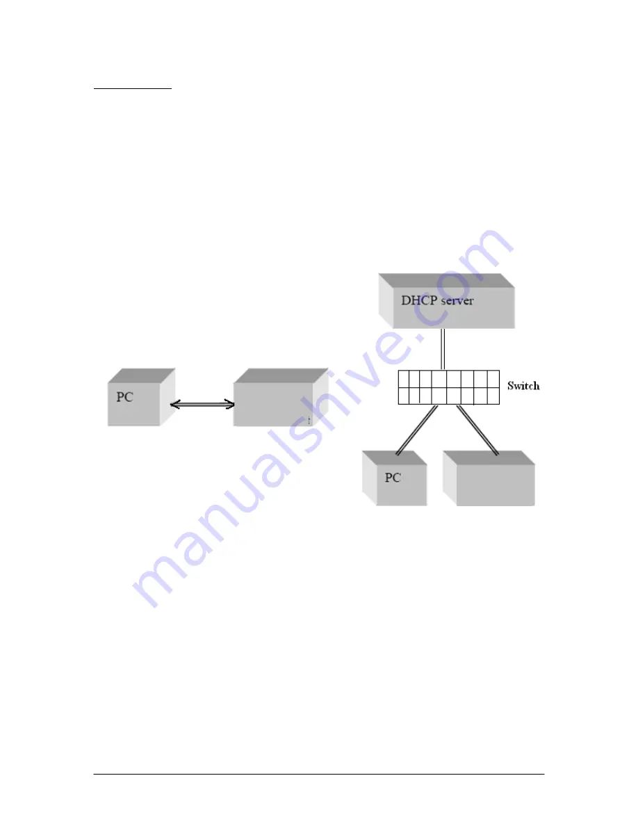
Static IP: the administrator assigns the instrument a fixed IP address. Using
this connection the instrument is directly connected to the controlling PC, as
shown in Figure 11. For this configuration, a cross-linked network cable must
be used.
b)
Dynamic IP: the DHCP server assigns the instrument an available address
when requested. Connect the instrument with a DHCP server (router or
exchange server), as shown in Figure 12. For this configuration, a standard
straight-linked network cable must be used.
Figure 11 Direct connection: PDLE-101 to PC
Figure 12 Connect PDLE-101 with DHCP server
2. Set Ethernet configuration and get IP address:
a)
Front panel:
As described in section 4.2, the user can set the PDLE for static or dynamic IP
addressing and query the IP address from the SETUP menu. Press the SETUP
button on the front panel. GET DYNAMIC IP sets the PDLE for dynamic IP
addressing and requests a dynamic IP address from the server. GET STATIC IP
sets the PDLE for static IP addressing and requests the static IP address stored in
memory.
The static IP address can be set from the front panel using the SET STATIC IP
option under the SETUP menu.
PDLE-101
PDLE-101
Содержание PDLE-101
Страница 31: ...3 Click Next 4 Click Next Document GP UM PDLE 101 11 Page 31 of 61 ...
Страница 32: ...5 Check Specify a location then click Next Document GP UM PDLE 101 11 Page 32 of 61 ...
Страница 36: ...12 Click Next 13 Click Finish Document GP UM PDLE 101 11 Page 36 of 61 ...
Страница 38: ...In this example the USB device is connected to COM3 Document GP UM PDLE 101 11 Page 38 of 61 ...
Страница 47: ... Properties on General tab Internet Protocol Properties Document GP UM PDLE 101 11 Page 47 of 61 ...
Страница 49: ... Properties on General tab Document GP UM PDLE 101 11 Page 49 of 61 ...


