®
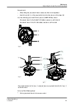
When the seat moves downwards (approx. 6 mm), the green LED on the
top of the control top will turn off to indicate that the position detection
device is detecting that the lower valve disk has left the closed position.
®
If the green LED does not go out, the position detection device is NOT set
correctly and the setting must be repeated, refer to the operating
instructions of the M/2.0 valve and .
®
Done
Step 3
Carry out the following steps:
1.
Activate the upper valve disk by activating solenoid valve Y3 via the PLC.
®
When the seat moves upwards (approx. 2 mm), the yellow LED on the
external proximity switch in the lantern will turn off to indicate that
proximity switch S3 is detecting that the upper valve disk has left the
closed position.
®
If the yellow LED does not turn off, the position detection device is NOT
set correctly and the adjustment procedure must be repeated as
described, see Section 7.7, Page 84.
®
Done
7.8.5
Test Procedure 2
Test procedure 2 is carried out by the Regulatory Inspector to verify that the
system interlock programmed in the PLC is working correctly by manually
actuating the valve disk that shuts off the pipe of the valve which currently is not
part of the cleaning circuit. If interlocking is implemented correctly, the CIP supply
pump or the source generating the cleaning solution pressure must switch off
automatically.
Hint!
Please note that test procedure 2 has to be performed with great care.
There is a danger of cleaning solution mixing with product if the
control system interlocks are not working correctly. Make sure that
there is no product in the valve body, which is not part of the active
CIP circuit, for the duration of the test!
Step 1
Make sure that the valve being tested is part of an active cleaning circuit and
determine which of the two housings is part of this active cleaning program.
Step 2
Carry out the following steps:
1.
If the upper housing is part of the active CIP circuit:
Activate lifting of the lower seat by activating solenoid valve Y2 via the PLC.
2.
If the lower housing is part of the active CIP circuit:
Activate lifting of the upper seat by activating solenoid valve Y3 via the PLC.
Start-up
Test procedure for Tuchenhagen PMO valves type M / 2.0
430BAL010697EN_2
88
15.04.2020
Содержание T.VIS M-15
Страница 6: ...430BAL010697EN_2 6 15 04 2020...
Страница 53: ...Fig 27 Assembly and installation Electrical connections 430BAL010697EN_2 15 04 2020 53...
Страница 55: ...Fig 28 Assembly and installation Electrical connections 430BAL010697EN_2 15 04 2020 55...
Страница 111: ...14 Spare parts list Switch bar T VIS M 15 Fig 82 Spare parts list Switch bar T VIS M 15 430BAL010697EN_2 15 04 2020 111...
Страница 119: ...Appendix 430BAL010697EN_2 15 04 2020 119...
Страница 120: ......


