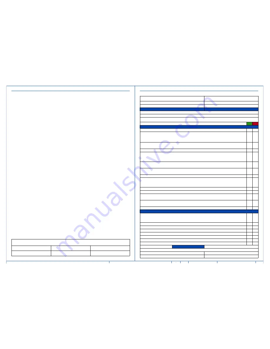
Customer Name:
PMI Name:
GON/SO Number:
Field Service Name:
Equipment:
Country/City or City/State:
Required site assessment milestones
Date of completion (dd/mm/yyyy)
1) Check site before Magnet Delivery
2) Check site before installation start
Place an "X" in either Y or N column
Site Ready Checks at Installation
Y
N
General Site Planning
Room dimensions, including ceiling height, for all Exam, Equipment/Technical & Control rooms meets GE specifications.
Ceiling support structure, if indicated on the GE drawing, is in the correct location and at the correct height according to the
of any GE supplied components. Overhead support Structure has been confirmed with customer/contractor to meet required
GE provided criteria.
Rooms that will contain equipment, including staging areas if applicable, are construction debris free. Precautions must be
taken to prevent debris from entering rooms containing equipment.
Finished ceiling is installed. If applicable ceiling tiles installed per PMI discretion.
Adequate delivery route from truck to final place of installation has been reviewed with all stakeholders, all
communications/notifications have occurred, arrangements have been made for special handling (rigging, elevator, fork lift,
etc.). All floors along delivery route will support weight of the equipment, temporary reinforcements arranged if needed.
System power & grounding (PDB/MDP) is available as per GE specifications, installed at point of final connection and ready to
use. Lock Out Tag Out is available.
System power and grounded audit has been scheduled to be completed during installation of equipment. (If Required) GEHC
PM to confirmed if needed.
Adequate room illumination installed and working.
Cable ways (floor/wall/ceiling/Access Flooring) are available for installation of GE cables and are of correct length and
diameter. Cable ways routes per GE Final drawings and cable access openings areas installed at a time determined by GEHC
PM. Surface floor duct can be installed at time of system installation.
HVAC systems Installed, and the site meets minimum environmental operational system requirements.
Network outlets installed and computer network available and working.
Hospital IT/connectivity contacts have been engaged and information has been added to Project management tool. (If
Required)
Floor levelness/flatness is measured and within tolerance, and there are no visible defects per GEHC specifications. Floor
Strength and thickness have been discussed with customer/contractor and they have confirmed GE requirements are met.
Customer supplied countertops where GE equipment will be installed are in place.
Specific for MR
RF Shield installed with possible exception of magnet entrance. RF Shield Effectivity and Ground Isolation Test needed. If GE
responsible for supplying RF shield, the RF shield Effectivity and Ground Isolation Test data is a Mandatory attachment into
MyProjects.
Power and connectivity is available for magnet monitoring.
Delivery route for He dewars & gradient coil cart to the scanning room is available.
Chilled water supply for Water Cooled Compressor or Air Cooled Compressor is ready and meets GE specifications.
Water drain available in the equipment room, if applicable.
Power for MR compressor & Chiller is available.
Ensure cryogen venting system is available for magnet connection.
Exhaust fan system is installed and operational per GE requirements.
Status of work
General comments
System can be delivered
PMI signature
Site ready for installation
FS signature: optional
GLOBAL SITE READINESS CHECKLIST (DI)
DOC1809666 Rev. 5
GENERAL SPECIFICATIONS
GE is not responsible for the installation of developers and associated equipment, lighting, cassette trays and
protective screens or derivatives not mentioned in the order.
The final study contains recommendations for the location of GE equipment and associated devices, electrical
wiring and room arrangements. When preparing the study, every effort has been made to consider every
aspect of the actual equipment expected to be installed.
The layout of the equipment offered by GE, the dimensions given for the premises, the details provided for
the pre-installation work and electrical power supply are given according to the information noted during
on-site study and the wishes expressed by the customer.
The room dimensions used to create the equipment layout may originate from a previous layout and may not
be accurate as they may not have been verified on site. GE cannot take any responsibility for errors due to
lack of information.
Dimensions apply to finished surfaces of the room.
Actual configuration may differ from options presented in some typical views or tables.
If this set of final drawings has been approved by the customer, any subsequent modification of the site must
be subject to further investigation by GE about the feasibility of installing the equipment. Any reservations
must be noted.
customer's responsibility to ensure that the site and final equipment placement complies with all applicable
local requirements.
All work required to install GE equipment must be carried out in compliance with the building regulations and
the safety standards of legal force in the country concerned.
These drawings are not to be used for actual construction purposes. The company cannot take responsibility
for any damage resulting therefrom.
CUSTOMER RESPONSIBILITIES
It is the responsibility of the customer to prepare the site in accordance with the specifications stated in the
final study. A detailed site readiness checklist is provided by GE. It is the responsibility of the customer to
ensure all requirements are fulfilled and that the site conforms to all specifications defined in the checklist and
up and ensure that actions in the checklist are complete, and if necessary, will aid in the rescheduling of the
delivery and installation date.
Prior to installation, a structrual engineer of record must ensure that the floor and ceiling is designed in such a
way that the loads of the installed system can be securely borne and transferred. The layout of additional
structural elements, dimensioning and the selection of appropriate installation methods are the sole
responsibility of the structural engineer. Execution of load bearing structures supporting equipment on the
ceiling, floor or walls are the customer's responsibility.
DISCLAIMER
THE UNDERSIGNED, HEREBY CERTIFIES THAT I HAVE READ AND APPROVED THE PLANS IN THIS DOCUMENT.
DATE
NAME
SIGNATURE
Date
Rev
/24
EN-MRI-TYP-SIGNA_EXPLORER-WEB.DWG
A
03/Aug/2018
SIGNA EXPLORER /SIGNA CREATOR
Typical
C2 - Disclaimer - Site Readiness
02


