


GE Medical Systems
Information Technologies
Responder 1000/1100
Page 11
/
38
Service Instruction
───────────────────────────────────────────────────────────────────
227 487 20 Rev G
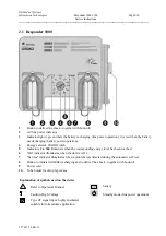
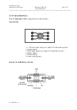
2.4 Mechanical Structure
The major mechanical components of the unit are the
top and bottom shell.
The top shell is the basic
element carrying the following sub-assemblies:
-
PCB Responder 1000/1100
-
Keypad (only Responder 1100)
The bottom shell holds the battery module and the capacitor which are linked to the PCB Responder
1000/1100 via cables.
The 6-pin inlet plug for
connecting the sync-cable
is located at the left side of the top shell. It is
linked to the PCB via a cable.
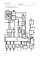
2.5 Functions
The functions follows the
Block Diagram
of the total unit
in chapter 2.3
and the
function blocks of
the P plans.
The unit contains following functions:
•
power supply
•
battery charger (located at PCB battery module)
•
on/off logic
•
voltage regulators
•
device control
•
LED indication
•
audio output
•
high voltage part
•
shock relay secure
•
relay interface
•
HV- oscillator
•
energy selection
•
voltage conversion HV-Cap
•
voltage conversion oscillator
•
energy ready indication
Содержание Responder 1000
Страница 1: ...Responder 1000 1100 Version V 1 0 Servicing Instructions 227 487 20 ENG Revision G ...
Страница 39: ......
Страница 40: ......
Страница 41: ......
Страница 42: ......
Страница 43: ......
Страница 44: ......
Страница 45: ......
Страница 53: ......
Страница 54: ......
Страница 56: ......
Страница 57: ......
Страница 58: ......
Страница 59: ......


