Chapter 2. CPU Features & Specifications
GFK-2222AD
April 2018
53
Hot Standby Redundancy
With firmware version 9.30 or later, it is possible to configure the CPE400 as a Hot Standby Redundancy
CPU with PROFINET IO. The two ports on LAN3 are used exclusively for this purpose: they provide a high-
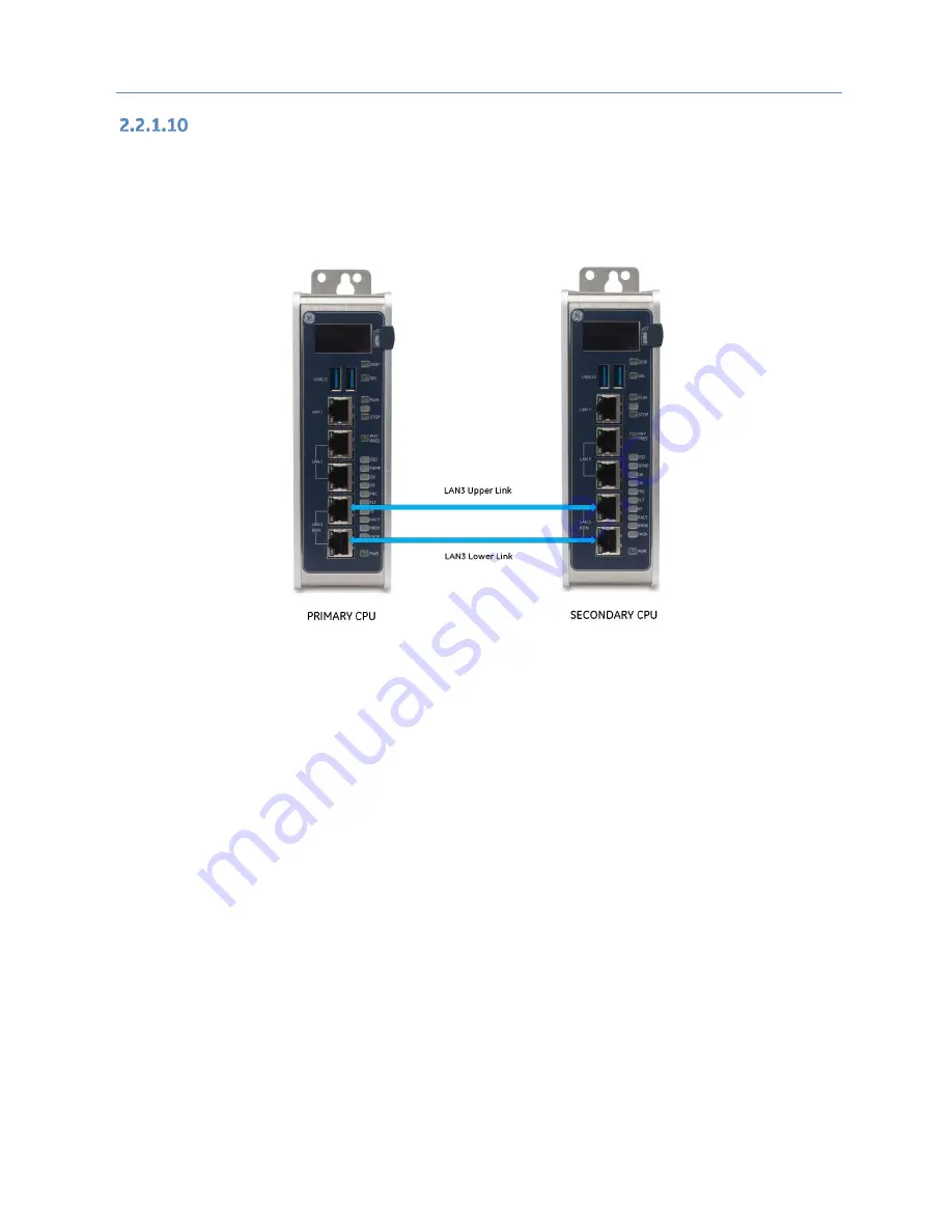
speed data synchronization link between the two CPUs. Connect the upper LAN3 port of the Primary
CPU to the upper LAN3 port of the Secondary CPU and connect the lower LAN3 port of the Primary to
the lower LAN3 port of the Secondary, as shown in Figure 13. Note that no additional hardware, other
than the two redundant CPUs, may be connected to LAN3.
Figure 13: LAN3 Interconnects for Hot Standby Redundancy
To enable redundancy in a CPE400 project, select the CPE400 target in the
PME Navigator
and use the
Property Inspector
to change the
Enable Redundancy
target property to
True
.
Important: Set the
Background Window Timer
to a minimum of 5ms in both the Primary and Backup
CPE400 hardware configurations. The
Background Window Timer
setting may be found on the
Scan
Tab
in the CPE400’s hardware configuration.
Once configured for HSB Redundancy, the RACT and RBOK LEDs (Figure 2) become functional.
•
RACT indicates the Local CPU is Ready & Active;
•
RBOK indicates the Remote CPU is Ready.
These two LEDs are also reflected in the Status Data of the CPU and are presented as OPC UA Variables.
The OLED display includes two menu items used in conjunction with Redundancy:
•
RDN Info provides status information via the OLED display.
•
RDN Command permits the operator to perform a Role Switch.
To support Hot Standby operations, LAN2 is configured as a PROFINET IO Controller. For additional
details, refer to Section 2.1.6,
For further details, refer to the
PACSystems Hot Standby CPU Redundancy User Manual
, GFK-2308 (rev
L or later).


