62
GE INFORMATION
D400 SUBSTATION GATEWAY INSTRUCTION MANUAL
CHAPTER 4: CONNECTING TO DEVICES AND NETWORKS
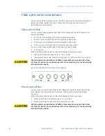
Fiber optic serial connections
For devices located some distance from the D400, they may be connected using glass or
plastic optical fiber cables. Fiber optic cabling also offers superior performance in
electrically noisy environments.
Glass optical fiber
You can use the following glass optical fiber (GOF) cabling with the D400 Glass Optical
Fiber Serial adapter:
•
50/125 µm core/cladding multi-mode (gradient index) cable
•
62.5/125 µm core cladding multi-mode (gradient index) cable
•
100/140 µm core/cladding multi-mode (gradient index) cable
•
200 m core Hard-Clad Silica (HCS) multi-mode (step index) cable
You can use the following fiber optic terminations for D400 cabling:
•
ST Connectors
When calculating cable length, consider the following optical power levels:
•
Glass optical fiber transmitter power is –19.0 ± 2 dBm
•
Glass optical fiber receiver sensitivity is typically –31.0 dBm over life of our product.
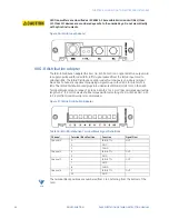
LED transmitters are classified as IEC 60825-1 Accessible Emission Limit (AEL) Class
1M. Class 1M devices are considered eye safe to the unaided eye. Do not view directly
with optical instruments.
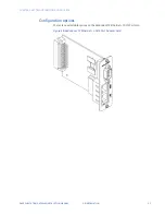
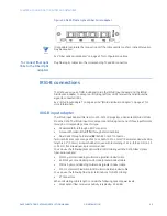
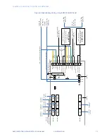
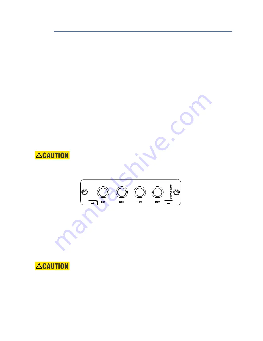
Figure 34: D400 Glass Optical Fiber Serial adapter
Plastic optical fiber
You can use 1 mm plastic optical fiber (POF) cabling with the D400 Plastic Optical Fiber
Serial adapter. The recommended termination is the Agilent Versatile Link Simplex
Connector.
When calculating cable length, consider the following optical power levels:
•
Plastic optical fiber transmitter power is –9.0 ± 4.5 dBm
•
Plastic optical fiber receiver sensitivity is typically –39 dBm
LED transmitters are classified as IEC 60825-1 Accessible Emission Limit (AEL) Class
1M. Class 1M devices are considered eye safe to the unaided eye. Do not view directly
with optical instruments.
Содержание Multilin D400
Страница 12: ...12 GE INFORMATION D400 SUBSTATION GATEWAY INSTRUCTION MANUAL PRODUCT SUPPORT ...
Страница 28: ...28 GE INFORMATION D400 SUBSTATION GATEWAY INSTRUCTION MANUAL CHAPTER 1 BEFORE YOU START ...
Страница 34: ...34 GE INFORMATION D400 SUBSTATION GATEWAY INSTRUCTION MANUAL CHAPTER 2 INSTALLING THE D400 ...
Страница 80: ...80 GE INFORMATION D400 SUBSTATION GATEWAY INSTRUCTION MANUAL CHAPTER 4 CONNECTING TO DEVICES AND NETWORKS ...
Страница 88: ...88 GE INFORMATION D400 SUBSTATION GATEWAY INSTRUCTION MANUAL CHAPTER 5 POWERING UP THE D400 ...
Страница 104: ...104 GE INFORMATION D400 SUBSTATION GATEWAY INSTRUCTION MANUAL CHAPTER 7 SETTING UP THE D400 FOR REDUNDANCY ...
Страница 118: ...118 GE INFORMATION D400 SUBSTATION GATEWAY INSTRUCTION MANUAL CHAPTER 9 ABOUT THE D400 APPLICATIONS ...
Страница 126: ...126 GE INFORMATION D400 SUBSTATION GATEWAY INSTRUCTION MANUAL CHAPTER 10 INTRODUCING THE D400 CONFIGURATION ...
Страница 158: ...158 GE INFORMATION D400 SUBSTATION GATEWAY INSTRUCTION MANUAL CHAPTER 12 USING THE D400 LOCAL CONFIGURATION UTILITY ...
Страница 174: ...174 GE INFORMATION D400 SUBSTATION GATEWAY INSTRUCTION MANUAL APPENDIX A STANDARDS PROTECTION ...
Страница 184: ...184 GE INFORMATION D400 SUBSTATION GATEWAY INSTRUCTION MANUAL APPENDIX C LIST OF ACRONYMS ...
Страница 192: ...192 GE INFORMATION D400 SUBSTATION GATEWAY INSTRUCTION MANUAL INDEX ...

