


106
GE INFORMATION
D400 SUBSTATION GATEWAY INSTRUCTION MANUAL
CHAPTER 8: USING THE D400
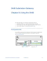
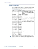
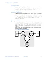
System status LEDs
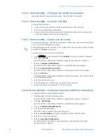
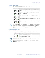
The System Status LEDs indicate the unit’s operational status:
NOTE
The NET2 ACT/LINK LEDs on the front panel may not be properly driven on the D400 Main
Module with FPGA revision V1.4 and earlier when using the Redundant TP Et COM2
Port card (GE Item No. 520-0218LF). To check the FPGA revision, enter
dmesg -s 16392 |
grep -i FPGA
at the
D400#>>
command prompt and search for FPGA in the output.
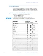
Serial port status LEDs
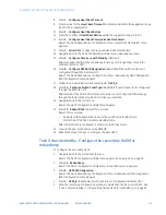
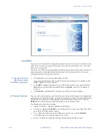
The Serial Port Status LEDs provide a visual indication of the status for each serial
communication port. For a given serial communication port:
NOTE
If a pair of LEDs is not lit, it does not indicate a problem, only that the connected device is
not active at that moment.
NOTE
If a serial communication card slot is empty, (that is, no card is installed) the serial Receive
(
RXD
) LED may be lit.
LED Display
Status Description
Power is correctly supplied to the unit (+5 V present on the D400 Main
Board).
Initialization (boot-up and self-diagnostics) of the D400 is complete and the
unit is ready to process data.
IRIG-B signal is being correctly processed. This LED flashes at a 2 Hz rate.
Link integrity for the Ethernet Switch in NET1 and NET2 slots. See note below.
Transmission activity for the Ethernet Switch in NET1 and NET2 slots. See
note below.
LED Display
Status Description
TXD
Serial transmission activity on the serial port
RXD
Serial reception activity on the serial port
Содержание Multilin D400
Страница 12: ...12 GE INFORMATION D400 SUBSTATION GATEWAY INSTRUCTION MANUAL PRODUCT SUPPORT ...
Страница 28: ...28 GE INFORMATION D400 SUBSTATION GATEWAY INSTRUCTION MANUAL CHAPTER 1 BEFORE YOU START ...
Страница 34: ...34 GE INFORMATION D400 SUBSTATION GATEWAY INSTRUCTION MANUAL CHAPTER 2 INSTALLING THE D400 ...
Страница 80: ...80 GE INFORMATION D400 SUBSTATION GATEWAY INSTRUCTION MANUAL CHAPTER 4 CONNECTING TO DEVICES AND NETWORKS ...
Страница 88: ...88 GE INFORMATION D400 SUBSTATION GATEWAY INSTRUCTION MANUAL CHAPTER 5 POWERING UP THE D400 ...
Страница 104: ...104 GE INFORMATION D400 SUBSTATION GATEWAY INSTRUCTION MANUAL CHAPTER 7 SETTING UP THE D400 FOR REDUNDANCY ...
Страница 118: ...118 GE INFORMATION D400 SUBSTATION GATEWAY INSTRUCTION MANUAL CHAPTER 9 ABOUT THE D400 APPLICATIONS ...
Страница 126: ...126 GE INFORMATION D400 SUBSTATION GATEWAY INSTRUCTION MANUAL CHAPTER 10 INTRODUCING THE D400 CONFIGURATION ...
Страница 158: ...158 GE INFORMATION D400 SUBSTATION GATEWAY INSTRUCTION MANUAL CHAPTER 12 USING THE D400 LOCAL CONFIGURATION UTILITY ...
Страница 174: ...174 GE INFORMATION D400 SUBSTATION GATEWAY INSTRUCTION MANUAL APPENDIX A STANDARDS PROTECTION ...
Страница 184: ...184 GE INFORMATION D400 SUBSTATION GATEWAY INSTRUCTION MANUAL APPENDIX C LIST OF ACRONYMS ...
Страница 192: ...192 GE INFORMATION D400 SUBSTATION GATEWAY INSTRUCTION MANUAL INDEX ...


