


20
Installation Instructions
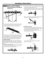
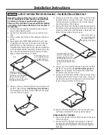
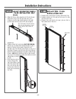
STEP 6 LEVEL UNIT
All models have 4-point leveling. The front is supported
by leveling legs; the rear is supported by adjustable
wheels. Both are accessible from the front of the unit.
• To level the back of the unit, turn the 7/16” hex nut
located above the front wheels. Turn clockwise
to raise or counterclockwise to lower the unit.
• For front leveling, use a 1-1/4” open-end wrench.
• Adjust height of unit to match installation cutout
opening 84-1/2”. The unit should be level and plumb
with cabinetry.
NOTE (Flush Installation Only): Raise appliance until
the case top comes in contact with the 1/2” spacer
block mounted to the underside of the cabinet soffit.
Appliance should be level at fully raised position.
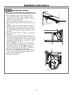
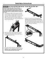
CAUTION
The rear leveling wheels and front leveling legs are
limited to a maximum height adjustment of 1”. If the
installation requires more than 84-1/2” height, the
installer should elevate the unit on a sheet of plywood
or runners. Cabinetry trim could also be added across
the top of the opening to shorten the opening. If you
attempt to raise the unit more than 1”, you will damage
the front leveling legs and the rear leveling wheels.
ATTENTION
Les roues de nivellement arrière et les pattes de
nivellement avant permettent un réglage maximal
de 25 mm (1 po). Si l’ouverture pour l’appareil
ménager a une hauteur supérieure à 2,15 m (84-1/2
po), l’installateur doit élever l’appareil ménager sur
une feuille de contre-plaqué ou des glissières. Il est
également possible d’ajouter des baguettes de finition
des placards sur le haut de l’ouverture afin de la
réduire. Lever l’appareil ménager de plus de 25 mm
(1 po) endommage les pattes de nivellement avant et
les roues de nivellement arrière.
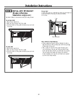
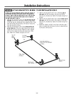
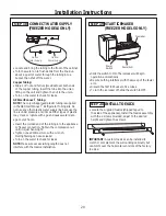
STEP 7 SECURE APPLIANCE
TO CABINETRY
Flush Installation Only
Whenever possible, perform this step for anti-tip security,
or when anti-tip brackets cannot be used. The appliance
must be secured to prevent tipping.
• Raise the grille panel to access the machine compart-
ment.
• For flush inset installation only, drill a hole in the case
top and drive a screw through the top into the adjacent
1/2” block.
Содержание Monogram ZIRS360NNLH
Страница 30: ...Notes 30...
Страница 31: ...Notes 31...