GE Monogram ZIRS360NNLH Скачать руководство пользователя страница 16

Installation Instructions

16

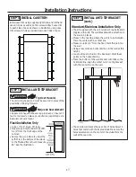
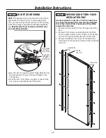
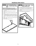
STEP 3  INSTALL SIDE PANELS

Skip this step when not using side panels
If you are using 1/4” side panels, they should be inserted 
into the case trim.

 STEP 1  REMOVE PACKAGING

WARNING


 Tip Over Hazard. 

Product is much heavier at the top than at the bottom 

– be careful when moving. When using a hand truck, 

handle from side only.

AVERTISSEMENT


 Risque de basculement  

Le produit est beaucoup plus lourd en haut qu’en bas. Il 

faut être prudent lors des déplacements. Si un diable est 

utilisé, il faut soulever le réfrigérateur sur le côté seule-

ment.
• Carefully cut banding at the top and bottom, remove 

outer carton.

• Slide out back corner posts (2).

• Slide carton off top of cabinet.

  NOTE: IT IS NOT NECESSARY TO LAY CABINET DOWN  

IN ORDER TO REMOVE SKID!

NOTE: DO NOT ATTEMPT TO ROLL UNIT OFF SKID.

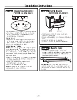
 STEP 2   INSTALL WATER LINE

• A cold water supply is required for automaticicemaker 

operation. The water pressure must be between 40 and 
120 p.s.i.

• Route 1/4” OD copper or GE SmartConnect

 plastic 

tubing between house cold water line and the water 
connection location.

• Tubing should be long enough to extend to the front of 

the unit. Allow enough tubing to accommodate bend 
leading into the water line connection.

NOTE: The only GE approved plastic tubing is supplied in 
the GE SmartConnect

 Refrigerator Tubing kits. Do not 

use any other plastic water supply line because the line 
is under pressure at all times. Other types of plastic may 
crack or rupture with age and cause water damage to 
your home.
GE SmartConnect

 Refrigerator Tubing Kits are available 

in the following lengths:
2’ (.6 m)      WX08X10002
8’ (2.4 m)    WX08X10006
15’ (4.6 m)  WX08X10015
25’ (7.6 m)  WX08X10025

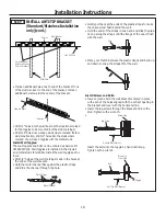
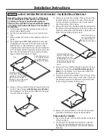
• The unit is secured to the skid with 4 slotted tie-down 

straps. Remove the four 5/16” bolts from the base 
channels in the tie-downs.

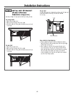
•  Remove toekick, custom handle trim, and wall brack-

et. Set aside for final installation.

• Lift the unit off the skid with an appliance dolly. 

Handle from the sides.

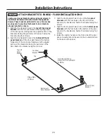
• Remove the four 7/16” bolts securing the tie-down 

brackets to the skid. 

NOTE: Commonwealth of Massachusetts Plumbing 
Codes 248CMR shall be adhered to. Saddle valves 
are illegal and use is not permitted in Massachusetts. 
Consult with your licensed plumber.

Shut off the main water supply.
Turn on the nearest faucet long enough to clear the line 
of water.
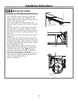
• Install a shut-off valve between the icemaker water 

valve and cold water pipe in a basement or cabinet. 
The shut-off valve should be located where it will be 
easily accessible.

• Turn on the main water supply and flush debris. Run 

about a quart of water through the tubing into a 
bucket. Shut off water supply at the shut-off valve.

NOTE: Saddle type shut-off valves are included in many 
water supply kits. Before purchasing, make sure a saddle 
type valve complies with your local plumbing codes. 

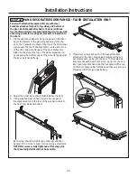
Fasten the panels to the unit with stick-on hook and 
loop fastener strips before setting unit in place.

Содержание Monogram ZIRS360NNLH

Страница 1: ...Installation Instructions 31 49062 1 224D2601P002 10 14 GE 36 Built In All Refrigerators and All Freezers monogram com...

Страница 2: ...could result in minor or moderate injury WARNING DANGER CAUTION For Monogram local service in your area call 1 800 444 1845 For Monogram service in Canada call 1 800 561 3344 For Monogram Parts and Ac...

Страница 3: ...syst me anti basculement AVERTISSEMENT Risque d explosion Conservez les mat riaux et vapeurs inflammables tels que l essence l cart de votre r frig rateur Le non respect de cette instruction peut ent...

Страница 4: ...Step 1 Remove Packaging 16 Step 2 Install Water Line 16 Step 3 Install Side Panels 16 Step 4 Install Case Trim 17 Step 5 Anti Tip Procedures 18 19 Step 6 Level Unit 20 Step 7 Secure Unit to Cabinetry...

Страница 5: ...back wall The water line should be 1 4 O D copper tubing or GE QuickConnect kit between the cold water line and water connection location long enough to extend to the front of the unit Installation o...

Страница 6: ...Cold Water Supply 24 Minimum Cutout Depth 84 1 2 Max Finished Opening 3 1 2 3 1 2 3 1 2 3 1 2 3 1 2 3 1 2 3 1 2 3 1 2 3 1 2 3 1 2 Clearances for Multiple Single Door Installations In a side by side in...

Страница 7: ...pply is recommended for each product Clearances for Multiple Single Door Installations In a side by side installation of a left and right door swing product a 1 clearance between the units is required...

Страница 8: ...inless Steel handles designed to fit 3 4 overlay panels ZKHPSS1 Pro Tubular Stainless Steel handle designed to fit 3 4 overlay panels ZUG2 For side by side installation of two trimmed models This kit...

Страница 9: ...l 18 lbs 1 2 1 2 1 1 4 1 1 1 4 1 Top Bottom Hinge Clearance Router 1 8 Deep Grille Panel Door Panel 38 9 5 8 69 13 16 CUSTOM HANDLE DESIGN GUIDE Flush Installation Only For custom handle installation...

Страница 10: ...be placed between the overlay and backer panel IMPORTANT NOTE Maximum total weight for assembled door panel is 67 pounds Maximum total weight for assembled grille panel is 11 pounds Assemble the pane...

Страница 11: ...el Dimensions A Width B Height 1 4 Framed Panel 69 7 8 8 7 8 Overlay Panel Dimensions A Width B Height 1 4 Backer Panel 69 7 8 8 7 8 0 10 Spacer Panel 68 1 2 7 5 8 3 4 Overlay Panel 70 1 8 9 IMPORTANT...

Страница 12: ...rd Installation Only Scale 1 1 Frameless Cabinets The case trim overlaps cabinets at the top and sides Therefore frameless cabinets may require filler strips to prevent interference with cabinet door...

Страница 13: ...nal Size Case Trim Refrigerator or Freezer Door Top View 90 DOOR SWING Standard Installation Only Scale 1 1 Frameless Cabinets The case trim overlaps cabinets at the top and sides Therefore frameless...

Страница 14: ...rounding plug which mates with a standard 3 prong grounding wall receptacle to minimize the possibility of electric shock hazard from this appliance Have the wall outlet and circuit checked by a quali...

Страница 15: ...Bracket Top Right Panel Bracket Bottom Left Panel Bracket Bottom Right Panel Bracket Top Left Panel Bracket Top Panel Bracket Bottom Door Bracket 4 Installed on door TOP IF HINGES ARE ON THE LEFT TOP...

Страница 16: ...r supply line because the line is under pressure at all times Other types of plastic may crack or rupture with age and cause water damage to your home GE SmartConnect Refrigerator Tubing Kits are avai...

Страница 17: ...e center of the studs Mark the wall at these points Installation Instructions 17 WARNING Tip Over Hazard The unit is top heavy and must be secured to prevent the possibility of tipping forward AVERTIS...

Страница 18: ...end of the bracket mark an additional hole towards the center of the bracket Drill 1 2 holes into the wall board at the locations marked for the toggles to be mounted not the stud markings Drill 3 16...

Страница 19: ...rward down and out to remove Power Cord Locate the power cord inside the left cavity If it has not been adjusted so the plug is easily accessible do so now Move Unit into Final Position Move appliance...

Страница 20: ...runners Cabinetry trim could also be added across the top of the opening to shorten the opening If you attempt to raise the unit more than 1 you will damage the front leveling legs and the rear leveli...

Страница 21: ...al position Do this to both sides Pull out on the end of the rod to make sure it is secure in the bracket Locate the hole on the rod that is closest to the unit A hair pin cotter will be put through t...

Страница 22: ...allation Instructions 22 Pin Location for 90 Door Swing Pin Location for 130 Door Swing Pin Location as Shipped for 115 Door Swing STEP 10 REMOVE DOOR TRIM FLUSH INSTALLATION ONLY Use the supplied Tor...

Страница 23: ...f door panel 7 Remove the tape from the panel Slide the templates to the bottom of the panel aligning the bottom sides and centerline of the panel with the bottom sides and cen terline of the template...

Страница 24: ...bracket with the four pilot holes at the bottom hinge side of the door panel making sure the angled portion of the bracket is facing the perimeter of the door Fasten the bracket using four screws 3 A...

Страница 25: ...he top of the panel brackets and gently allow the bottom edge of the panel to lay against the door as it hangs freely 2 Adjust the panel by pushing it flush against the door 3 Using supplied washer he...

Страница 26: ...he grille panel with the lettering face up Align the top side and cen terline of the template with the top side and centerline of the door Tape the template in place using masking tape 5 Using a 1 8 w...

Страница 27: ...ning Check the gap by closing the door 3 Check that the door panel is in plane with the face of the cabinets The panel can be adjusted outward by turning the set screw threaded into the tab of the doo...

Страница 28: ...side washer head screws NOTE Over tightening washer head screws may result in bending wood panel brackets as well as misaligning wood door panels 7 Drive the door anchor screws through the two white p...

Страница 29: ...e tubing into the appliance or freezer connection Tighten the compression nut until it is just hand tight Tighten one additional turn with a wrench Overtightening can cause leaks Turn on the water to...

Страница 30: ...Notes 30...

Страница 31: ...Notes 31...

Страница 32: ...e worn For Monogram local service in your area call 1 800 444 1845 NOTE Product improvement is a continuing endeavor at General Electric Therefore materials appearance and specifications are subject t...

Отзывы: