background image


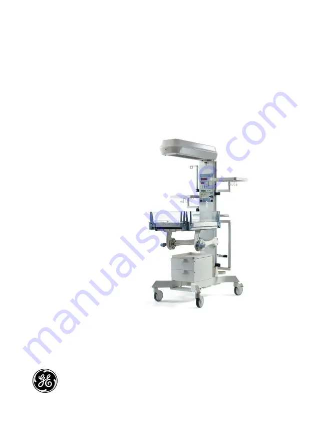
Lullaby™ Warmer   
Maintenance and Service Manual -English   

2042376-001 
Rev G


GE Healthcare 

 
Lullaby™ Warmer  


Maintenance and Service manual  


Содержание Lullaby Warmer

Страница 1: ...Lullaby Warmer Maintenance and Service Manual English 2042376 001 Rev G GE Healthcare Lullaby Warmer Maintenance and Service manual ...

Страница 2: ... or discontinue the product described at any time without notice or obligation Contact your GE Representative for the most current information Lullaby is a trademark owned by Datex Ohmeda Inc GE and GE Monogram are trademarks of General Electric Company All other company and product names mentioned may be trademarks of the companies with which they are associated ...

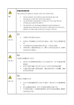
Страница 3: ...ие може да доведе до нараняване на доставчика на услугата оператора или пациентa в резултат на токов удар механична или друга опасност ZH CN 警告 本维修手册仅提供英文版本 如果客户的维修服务人员需要非英文版本 则客户需自行提供翻译服 务 未详细阅读和完全理解本维修手册之前 不得进行维修 忽略本警告可能对维修服务人员 操作人员或患者造成电击 机械伤 害或其他形式的伤害 ZH HK 警告 本服務手冊僅提供英文版本 倘若客戶的服務供應商需要英文以外之服務手冊 客戶有責任提供翻 譯服務 除非已參閱本服務手冊及明白其內容 否則切勿嘗試維修設備 不遵從本警告或會令服務供應商 網絡供應商或病人受到觸電 機械 性或其他的危險 ZH TW 警告 本維修手冊僅有英文版 ...

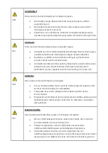
Страница 4: ...isu obslužného personálu nebo pacientů vlivem elektrického proudu respektive vlivem mechanických či jiných rizik DA ADVARSEL Denne service manual findes kun på engelsk Hvis en kundes tekniker har brug for et andet sprog end engelsk er det kundens ansvar at sørge for oversættelse Forsøg ikke at servicere udstyret uden at læse og forstå denne servicemanual Manglende overholdelse af denne advarsel ka...

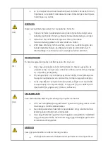
Страница 5: ...oiatuse eiramine võib põhjustada teenuseosutaja operaatori või patsiendi vigastamist elektrilöögi mehaanilise või muu ohu tagajärjel FI VAROITUS Tämä huolto ohje on saatavilla vain englanniksi Jos asiakkaan huoltohenkilöstö vaatii muuta kuin englanninkielistä materiaalia tarvittavan käännöksen hankkiminen on asiakkaan vastuulla Älä yritä korjata laitteistoa ennen kuin olet varmasti lukenut ja ymmä...

Страница 6: ...ιρίδιο σε γλώσσα εκτός των αγγλικών αποτελεί ευθύνη του πελάτη να παρέχει τις υπηρεσίες μετάφρασης Μην επιχειρήσετε την εκτέλεση εργασιών σέρβις στον εξοπλισμό αν δεν έχετε συμβουλευτεί και κατανοήσει το παρόν εγχειρίδιο σέρβις Αν δεν προσέξετε την προειδοποίηση αυτή ενδέχεται να προκληθεί τραυματισμός στον τεχνικό σέρβις στο χειριστή ή στον ασθενή από ηλεκτροπληξία μηχανικούς ή άλλους κινδύνους H...

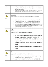
Страница 7: ...o a provvedere direttamente alla traduzione Procedere alla manutenzione dell apparecchiatura solo dopo aver consultato il presente manuale ed averne compreso il contenuto Il mancato rispetto della presente avvertenza potrebbe causare lesioni all addetto alla manutenzione all operatore o ai pazienti provocate da scosse elettriche urti meccanici o altri rischi JA このサービスマニュアルには英語版しかありません サービスを担当される業者...

Страница 8: ...ų suteikti vertimo paslaugas privalo klientas Nemėginkite atlikti įrangos techninės priežiūros jei neperskaitėte ar nesupratote šio eksploatavimo vadovo Jei nepaisysite šio įspėjimo galimi paslaugų tiekėjo operatoriaus ar paciento sužalojimai dėl elektros šoko mechaninių ar kitų pavojų NO ADVARSEL Denne servicehåndboken finnes bare på engelsk Hvis kundens serviceleverandør har bruk for et annet sp...

Страница 9: ...os ou outros PT PT ATENÇÃO Este manual de assistência técnica só se encontra disponível em inglês Se qualquer outro serviço de assistência técnica solicitar este manual noutro idioma é da responsabilidade do cliente fornecer os serviços de tradução Não tente reparar o equipamento sem ter consultado e compreendido este manual de assistência técnica O não cumprimento deste aviso pode colocar em peri...

Страница 10: ...n da obezbedi prevodilačke usluge Ne pokušavajte da opravite uređaj ako niste pročitali i razumeli ovo servisno uputstvo Zanemarivanje ovog upozorenja može dovesti do povređivanja servisera rukovaoca ili pacijenta usled strujnog udara ili mehaničkih i drugih opasnosti SK UPOZORNENIE Tento návod na obsluhu je k dispozícii len v angličtine Ak zákazníkov poskytovateľ služieb vyžaduje iný jazyk ako an...

Страница 11: ...teknikern operatören eller patienten till följd av elektriska stötar mekaniska faror eller andra faror SL OPOZORILO Ta servisni priročnik je na voljo samo v angleškem jeziku Če ponudnik storitve stranke potrebuje priročnik v drugem jeziku mora stranka zagotoviti prevod Ne poskušajte servisirati opreme če tega priročnika niste v celoti prebrali in razumeli Če tega opozorila ne upoštevate se lahko z...

Страница 12: ...This page is left blank intentionally ...

Страница 13: ...PROCEDURES 16 2 1 MECHANICAL CHECKS 16 2 2 CONTROLLER CHECKS 20 2 3 ACCESSORIES CHECK 21 CHAPTER 3 MAINTENANCE AND CLEANING 22 3 1 REPAIR POLICY 22 3 2 REQUIRED TOOLS AND PERSONNEL PROTECTION EQUIPMENT 22 3 3 MAINTENANCE SCHEDULE 22 3 4 CLEANING INSTRUCTIONS 23 3 5 CLEANING THE LULLABYTM WARMER 25 3 6 CLEANING SOLUTIONS 27 3 7 CLEANING AND DISINFECTING INDIVIDUAL COMPONENTS 27 3 8 CLEANING OTHER C...

Страница 14: ...DURES 61 7 1 REPLACING THE PARTS OF THE LULLABYTM WARMER 61 7 1 1 Replacing the Hood Exterior FRU Kit No 2043936 001 61 7 1 2 Replacing the extrusions 62 7 1 3 Replacing the hood spacer hood top plate and observation lamp plate 63 7 1 4 Replacing the Front Bracket 64 7 1 5 Replacing the Front and Rear Covers 65 7 1 6 Replacing the PCB Wire Assembly PWA FRU Kit No 2043951 001 66 7 1 7 Replacing the...

Страница 15: ...U Kit No 2043950 001 94 7 1 23 Replacing the Cable Harness FRU FRU Kit No 2062276 001 for 230V 115V and for 100V 95 7 1 24 Replacing the SMPS FRU 2062282 001 96 CHAPTER 8 FRU PARTS 97 CHAPTER 9 ILLUSTRATED PARTS 106 9 1 ELECTRICAL WIRING DIAGRAM 106 9 2 BLOCK DIAGRAM 108 9 3 HOOD ASSEMBLY 110 9 4 BASE ASSEMBLY 115 9 5 BED ASSEMBLY 121 CHAPTER 10 PRODUCT LABELS 122 APPENDIX A 126 TEMPERATURE CONVER...

Страница 16: ...xvi 2042376 001 Rev G 2012 General Electric Company All rights reserved LullabyTM Warmer WARRANTY 138 GE SERVICE CENTERS 139 ...

Страница 17: ...Manual Mode 6 Figure 11 Baby Mode 7 Figure 12 Displays 8 Figure 13 Keys 9 Figure 14 Power Standby ON Switch 10 Figure 15 Power Standby ON Switch 10 Figure 16 Alarms 11 Figure 17 Global Alarm 12 Figure 18 Check Baby Alarm 12 Figure 19 Probe Failure Indicator 13 Figure 20 System Heater Failure Alarms 14 Figure 21 OVR 15 Figure 22 UVR 15 Figure 23 Heat OFF Indicator 15 Figure 24 Power Failure Indicat...

Страница 18: ... Probe 21 Figure 41 Checking the Accessories 21 Figure 42 Opening the drawer 21 Figure 43 The Hood 24 Figure 44 Removing the Plexiglas 25 Figure 45 Removing the Mattress 25 Figure 46 Removing the Plexiglas 26 Figure 47 Cleaning With Ear Bud 26 Figure 48 Removing the X Ray Tray 26 Figure 49 Unpacking the LullabyTM Warmer shipper box 38 Figure 50 Contents of LullabyTM Warmer shipper box 39 Figure 51...

Страница 19: ...unting Bracket 52 Figure 72 Mounting Cylinder 52 Figure 73 Mounting the Drawer Assembly 53 Figure 74 Mounting the Chest Tube Drainage Hanger 54 Figure 75 Mounting the Tubing Management Arm 54 Figure 76 Mounting the Utility Pole 55 Figure 77 Mounting the Basket Assembly 55 Figure 78 Mounting the Resuscitation Bag Clip 55 Figure 79 Mounting the Resuscitation Bag Clip 56 Figure 80 Assembling the Slot...

Страница 20: ...ng the Plate Power Inlet 93 Figure 99 Replacing the Cable Harness 94 Figure 100 Replacing the Cable Harness 95 Figure 101 Replacing the SMPS 96 Figure 102 Electrical Wiring Diagram 107 Figure 103 Block Diagram 109 Figure 104 Hood Assembly 1 110 Figure 105 Hood Assembly 2 110 Figure 106 Hood Assembly 3 111 Figure 107 Hood Assembly 4 111 Figure 108 Base Assembly 1 115 Figure 109 Base Assembly 2 116 ...

Страница 21: ...ce to the LullabyTM Warmer before performing service or maintenance procedures Apply power only if you are specifically instructed to do so as part of the procedure Service Only competent individuals trained in the repair of this equipment should attempt to service it as detailed in this manual Detailed information for more extensive repairs is included in this manual solely for the purpose of use...

Страница 22: ...edge and experience with devices of this nature There are no user serviceable parts in the LullabyTM Warmer Repairs should be undertaken only by qualified personnel Genuine replacement parts manufactured or sold by GE Healthcare must be used for all repairs Read through each step in every procedure before starting any exceptions may result in a failure in safely completing the attempted procedure ...

Страница 23: ...LullabyTM Warmer Symbol Description Type B Equipment Functional Earth Terminal Protection Earth Terminal Alternating Current European Union Representative Refer to instruction manual booklet Catalog Number or Orderable Part Number Serial Number Manufacturer Date of manufacture WEEE Symbol Prescription Device Label for United States Do not reuse single use only ...

Страница 24: ...byTM Warmer Baby Mode Temperature Increase Decrease Manual Mode Heater power indication in bar graph displayed in intervals of every 20 APGAR Start Pause APGAR Reset Alarm Silence Baby Temperature Heater System Failure Skin Probe Failure Disconnect Power Failure Observation Lamp ...

Страница 25: ...ay Maximum load capacity WARNING For e g maximum load capacity should be less than 2 2 kg as shown in the figure WARNING Do not hang items on to the heater housing WARNING Pull the knob to swivel the heater hood WARNING Dovetail rail capacity Maximum 14 kg WARNING Keep your head out of the way when the hood is being swiveled to the right or left ...

Страница 26: ...ng the LullabyTM Warmer Chapter 5 System Installation Procedure Provides information on installing the LullabyTM Warmer Chapter 6 System Dismantling Procedure Provides information about dismantling the LullabyTM Warmer Chapter 7 Field Replacing Unit FRU Replacement Procedure Describes procedures to replace the FRUs of the LullabyTM Warmer Chapter 8 FRU Parts Provides information about the FRU part...

Страница 27: ...cket with protective cover Patient skin temperature probe Optional Feature includes Drawer system with under bed storage Accessories Figure 1 LullabyTM Warmer 1 1 Indications for Use Intended Use Infant radiant warmers provide infrared heat in a controlled manner to neonates and infants who are unable to maintain appropriate thermo regulation based on their own physiology Infant radiant warmers ma...

Страница 28: ...Instrument tray optional 5 Heater hood 6 IV pole optional 7 Basket assembly optional 8 Mattress 9 Slotted window panel optional 10 X ray tray 11 Drawer package Optional Feature Number Description 12 Control panel 13 Observation light switch 14 Hood swivel knob 15 Dovetail rail 16 Skin probe socket with protective cover 17 Power standby ON switch 18 Utility pole Optional 19 Drainage hanger assembly...

Страница 29: ...Figure 4 Side View Figure 5 Back View Feature Number Description 21 Bedside panel 22 Bed tilt handle 23 Castor 24 Height skirt Feature Number Description 25 Maneuvering handle and cord wrap 26 Power inlet plug 27 Electrical component enclosure 28 Equipotent stud 24 23 23 22 21 25 26 28 27 ...

Страница 30: ...arms and indicators 3 Observation light switch 4 Control modes and indication 5 APGAR keys 6 Alarm silence indicator 7 Alarms silence key 8 Skin probe socket with protective cover 9 Power Standby ON switch Feature Number Description 1 Baby temperature Displayed in Degree Celsius 2 Control temperature Displayed in Degree Celsius 3 Baby Mode LED indicator 4 Baby Mode key To select Baby Mode 5 Heater...

Страница 31: ...Figure 9 APGAR Feature Number Description 9 Global alarm 10 Check baby alarm 11 Heater failure alarm 12 Probe failure disconnect alarm 13 Power failure alarm 14 Alarm silence indicator 15 Alarm silence key Feature Number Description 16 APGAR timer display 17 APGAR start pause 18 APGAR reset 18 16 17 14 10 11 12 13 15 9 ...

Страница 32: ...eater output setting after a systematic power down The Manual Mode is indicated by the green indicator located above the Manual Mode key as seen in the figure The percentage of full heater output can be adjusted in 5 increments using the Temperature increase decrease keys which are between the two control mode keys Heater output increments show up in the bar graph as lit up LEDs The baby s skin te...

Страница 33: ... differences between the set temperature and the skin probe temperature reading You can enter desired set temperatures from 30 38 C using the Temperature increase decrease keys which are located between the two control mode keys This value is shown in the set temperature display The Baby s actual temperature is shown in the upper display i e Baby Temperature display The Baby Mode is indicated by t...

Страница 34: ...aby temperature measurement Control temperature display indicates the control temperature the user selects in the Baby Mode The baby temperature range is from 30 0 38 0 C The control temperature display is not active in the Manual Mode Power bar graph indicates power level selected in increments of 5 APGAR timer display indicates clocked time in minutes and seconds up to a maximum of 60 minutes Th...

Страница 35: ...vel power in the Manual Mode and to set the control temperature in the Baby mode Alarm silence key This key is used to silence the audible alarm It silences all alarms except the system failure alarm Start Hold switch This switch activates the clocked timer At the first instance of pressing this switch the clocked timer is activated At the second instance it holds the clocked timer At the third in...

Страница 36: ...scription Figure 14 Power Standby ON Switch Observation light standby ON switch This switch activates the observation light located in the heater hood Figure 15 Power Standby ON Switch Power standby ON switch This switch turns on the heater located in the hood Observation Light Standby ON Switch Power Standby ON Switch ...

Страница 37: ...ept the power failure alarm are alternating single tone alarms The alarms are listed below Global alarm Check Baby alarm Probe Failure alarm Heater System Failure alarm Power Failure alarm The alarms are depicted in figure 16 Figure 16 Alarms Probe Failure Disconnect Global Alarm Check Baby Alarm System Heater Failure Power Failure ...

Страница 38: ...put has been raised to an output level greater than 25 continuously for 12 minutes The alternating single tone alarm is activated for this condition and heater output is reduced to 25 Pressing the Alarm Silence key silences this alarm and resets the timer for another 12 minutes of operation and restores the heat level to previous setting In the Manual Mode with the skin probe connected if the baby...

Страница 39: ...e temperature of the baby stays at less than 30 C for more than 3 minutes the Check Baby alarm activates with both audio and visual indication The heater will also be cut off Pressing the silence key will mute the audible alarm switches off the visual indication and restores the controlled heating Figure 19 Probe Failure Indicator Probe Failure Disconnect Alarm The Probe Failure alarm is active du...

Страница 40: ... the set temperature display During power up process if there is a failure with relay rLy is displayed on the set temperature display and with Triac failure trC is displayed on the Set Temperature display as seen in Figure 20 If a key is stuck key is displayed on the Set Temperature display If there is a mismatch between the heater element and voltage configuration CFg is displayed on the Set Temp...

Страница 41: ...aby unattended while ovr is displayed as heater will be turned off If the applied voltage is lower than the rated voltage by 10 for atleast 1 minute UVR is displayed on the set temperature display as seen in Figure 22 In this condition temperature monitoring and all other warmer functions are present Figure 23 Heat OFF Indicator Heat OFF indication When the hood is rotated to either of the sides t...

Страница 42: ...echanical Checks WARNING Before using the LullabyTM Warmer read this manual Attempting to use device without a thorough understanding of its operation may result in patient or user injury WARNING Do not perform the preoperational checkout procedure while the patient occupies the LullabyTM Warmer WARNING Complete the preoperational checkout procedure section of this manual before putting the Lullab...

Страница 43: ...the power cord for any signs of damage Replace the cord if damage is evident NOTE Use the handle to wrap the power cord when the LullabyTM Warmer is being moved Figure 27 Inspecting the LullabyTM Warmer Examine the warmer overall for any damaged or missing parts NOTE Figure 25 displays the warmer with all the accessories mounted These accessories IV pole Utility pole Cylinder holder and Monitor In...

Страница 44: ...A and check that they hold the unit in place 2 Release the brakes as seen in Figure 28B and check that the unit moves smoothly Check that all the casters are in firm contact with the floor and that the unit is stable by locking the caster brakes Figure 29 Inspecting the Bedside Panel Check the operation of the four bedside panels Figure 30 Inspecting the Bedside Panel Lock The bedside panels shoul...

Страница 45: ...2 When the rotation of the bed tilt handle is stopped the bed should stay in position at any angle along its tilt path as seen in Figure 33 Figure 34 Hood Swivel right Figure 35 Hood Swivel left Figure 36 Hood Lock Checking the heater hood swivel To check the operation of the heater hood swivel pull the knob and swivel the heater hood on either side as seen in Figure 34 and Figure 35 Ensure that t...

Страница 46: ...OTE Power outlets are region specific Figure 38 Patient Probe Connection Connect the patient probe to the jack on the control panel NOTE Insert the probe completely into the jack till you hear a click Figure 39 Power Standby ON Switch Switch on the Power Standby ON switch located on the control panel Check that All the displays and indicators light Heater level bar graph is 100 Audible beeps will ...

Страница 47: ...tween your fingers and then verify the increase in baby temperature reading 2 3 Accessories Check Illustration Description Figure 41 Checking the Accessories Check that the accessories are securely mounted as seen in Figure 41 Figure 42 Opening the drawer If the drawer package is installed check that all the drawers open and close freely as seen in Figure 42 ...

Страница 48: ...epresentative or by a competent trained person who has experience in repairing devices of this nature Refer to the list of service parts and for instructions on how to service and calibrate the LullabyTM Warmer in this manual After service follow the checkout procedures before using the LullabyTM Warmer CAUTION Detailed information for more extensive repairs is included in this manual solely for t...

Страница 49: ... reflector heater duct and center pillar are required to be safety ground bonded When servicing involves disturbing the ground bonds of these components the ground integrity should be verified Earth Leakage and Chassis Leakage Current For 220 230 240 V AC rated devices In normal condition and in all possible operating modes the earth leakage current shall be less than 500 microamperes If required ...

Страница 50: ...erature probes to disinfect them These guidelines are designed to complement and are not meant to replace hospital infection control policies Cleaning Instructions After each patient use follow your hospital s infection control procedures for surface disinfection Wipe down the surfaces of the LullabyTM Warmer with a soft cloth dampened with a cleaning solution Refer to Section 3 6 Cleaning Solutio...

Страница 51: ...ction equipment 2 Unplug the power cord Move the LullabyTM Warmer to an area where you have adequate space to get around and clean 3 Clean the surface of the LullabyTM Warmer using mild detergent solution applied with a damp cloth or sponge 4 Do not allow liquids to seep into the electrical housing 5 Remove all the accessories and the patient temperature probe 6 Empty the drawers 7 Figure 44 Remov...

Страница 52: ...ton swabs cleaning wipes or hospital suggested aids to ensure visible cleanliness of all areas 11 Figure 48 Removing the X Ray Tray Remove the X ray tray to clean it 12 Chemically disinfect and dry the control panel 13 Chemically disinfect and dry the dovetail rails 14 Remove the drawers immerse in soap solution wash and wipe after complete drying to remove residue Also follow cleaning manufacture...

Страница 53: ...vents such as acetone CAUTION Do not spray cleaning solutions directly on the LullabyTM Warmer CAUTION Apply the cleaning solution with a clean sponge or cloth Do not allow liquids to seep into the heater housing CAUTION Always dry the surfaces with a clean damp soft cloth to avoid scratches and remove any residue of the cleaning solution left after cleaning 3 7 Cleaning and Disinfecting Individua...

Страница 54: ...ents after cleaning NOTE Disposable skin temperature probes cannot be cleaned and are intended for single patient use 3 8 Cleaning Other Components CAUTION Do not clean the LullabyTM Warmer with organic solvents scouring compounds strong acids or strong bases These compounds may damage the components CAUTION To minimize the generation of static electricity do not polish the bedside panels with a d...

Страница 55: ...amp 2039891 001 in FRU 2043950 001 NOTE For Warmer with halogen lamp and transformer Replace cable assembly heater observation lamp 2060529 001 in FRU 2062276 001 NOTE For Warmer with SMPS and LED observation lamp Heater cable is disconnected from the PWA Connect heater observation lamp cable to PWA PCB Wire Assembly Check if the heater tube resistance is above 100 ohms If yes replace heater tube ...

Страница 56: ...ith SMPS and LED observation lamp Replace SMPS from FRU 2062282 001 Improper connection of connector P2 on PWA Check the connection on the PWA Defective PWA Replace PWA FRU 2043951 001 NOTE For Warmer with halogen lamp and transformer Replace PWA FRU 2062277 001 NOTE For Warmer with SMPS and LED observation lamp Defective System Power Standby ON switch harness Replace the System Power Standby ON s...

Страница 57: ...he lamp switch cable from the front panel to the PWA is damaged Replace the observation lamp switch cable harness 2039890 001 in FRU 2043950 001 NOTE For Warmer with halogen lamp and transformer Replace cable assembly 2060528 001 in FRU 2062276 001 NOTE For Warmer with SMPS and LED observation lamp Defective cable assembly heater observation lamp Replace cable assembly heater observation lamp 2039...

Страница 58: ...FRU 2062278 001 for 230V Replace 8A fuse in PWA from FRU 2062278 001 for 115V Replace 10A fuse in PWA from FRU 2062278 001 for 100V Config plug is missing or defective NOTE For Warmer with halogen lamp and transformer If yes Replace Config plug 2039935 001 in FRU 2043950 001 Fuse F1 on the PWA is defective NOTE For Warmer with halogen lamp and transformer Replace PWA FRU 2043951 001 CR12 on the PW...

Страница 59: ...951 001 NOTE For Warmer with halogen lamp and transformer Replace PWA FRU 2062277 001 NOTE For Warmer with SMPS and LED observation lamp Defective probe jack on PWA Replace PWA FRU 2043951 001 NOTE For Warmer with halogen lamp and transformer Replace PWA FRU 2062277 001 NOTE for warmer with SMPS and LED observation lamp Heater hood does not swivel Hood is not aligned to center Align the heater hoo...

Страница 60: ...p and transformer Replace PWA FRU 2062277 001 NOTE For Warmer with SMPS and LED observation lamp When the LullabyTM Warmer is switched on rLy is displayed on the Control Temperature display with alarm indication The safety relay is defective Replace PWA FRU 2043951 001 NOTE For Warmer with halogen lamp and transformer Replace PWA FRU 2062277 001 NOTE For Warmer with SMPS and LED observation lamp W...

Страница 61: ...eater is cut off when Hood is at center position with system failure LED blinking without alarm Swivel sensing cable not connected Connect Swivel sensing cable Swivel sensing cable is defective Replace Swivel sensing cable 2044356 001 in FRU 2043950 001 NOTE For Warmer with halogen lamp and transformer Replace Swivel sensing cable 2060526 001 in FRU 2062276 001 NOTE For Warmer with SMPS and LED ob...

Страница 62: ...nel Protection Equipment PPE 5 2 Contents of LullabyTM Warmer Packaging Verify the following are included in the main packaging box Also refer to order list placed by the customer and to specific instructions before unpacking the box CAUTION Always use the personnel protection equipment when installing dismantling servicing and conducting maintenance of the warmer Sl No Description 1 Standard serv...

Страница 63: ...head screw 4 per set M5 flat washer 4 per set M5 spring washer 4 per set Service manual 1 Operator manual 1 Height adjustment Pin 1 Power cord 1 Utility post 3 5 Optional 1 Leg and Pillar assembly Leg assembly 1 Pillar assembly 1 Accessories IV Pole assembly Optional 1 Utility Pole assembly Optional 1 Monitor assembly Optional 1 Drawer assembly Optional 1 MSB drawer assembly Optional 1 Cylinder Ho...

Страница 64: ...box check if all the contents are present If any of the contents listed in the contents table is missing contact your local customer care at the number provided at the end of this document If it is a sea shipment uncover the shipment foil and then proceed with the unpacking Figure 49 Unpacking the LullabyTM Warmer shipper box Packaging Parts Description Quantity Laurel Orderable Accessories Resusc...

Страница 65: ...ctions given below to unpack the warmer shipper box 1 Cut open the six straps on wooden or eight straps on corrugated packing box 2 Remove the lid and lift the side enclosure of the packing box 3 If the packaging is seaworthy cut the aluminum foil shrink wrap 4 Cut open the straps on the corrugation boxes and the accessories 5 Separate the Hood Bed packing boxes and accessories Leg Assembly Pillar...

Страница 66: ...ng so that you can use it to repack the warmer when it is being transported locally WARNING In the assembled condition Heater hood and bed assembled the LullabyTM Warmer should not be subjected to outdoor transport 5 4 Pillar to Leg Assembly and Height Adjustment WARNING Apply castor brakes before installing the LullabyTM Warmer Illustration Description Figure 52 Pillar Assembly To assemble the pi...

Страница 67: ...y 4 Slide the pillar assembly over the leg assembly through the base C support 5 Use the handle or fulcrum to lift the base assembly to the desired height Note To fix the warmer bed at the desired height align the holes as described in the procedure to adjust the height of the warmer bed 6 Align the holes on the pillar assembly with the holes on the leg assembly 7 Insert the height adjustment pin ...

Страница 68: ...llar to Leg Assembly Description The bed can be adjusted to three desired heights Lowest Height 880mm Mid Height 950mm Top Height 1020 mm There is a difference of 70 mm between the consecutive heights Note The height levels mentioned here are measured from the floor to the surface of the mattress WARNING 1 Do not attempt to adjust the height of the bed after the hood and bed are fixed to the base ...

Страница 69: ...d 43 Illustration Description Instructions to adjust height 1 Remove the fasteners 2 Press open the snap of height skirt 3 Match the hole insert the height adjustment pin for the required height 4 Tighten the M8 QTY 6 fasteners 5 Press to assemble the snaps 6 Fasten the M5 screws Snap ...

Страница 70: ... Tooth washers Qty 4 M8 Box Spanner Instructions to assemble the base and the bed 1 Position the bed base assembly on the bed tilt mechanism as shown in Figure 56 2 Fasten the M8 Nyloc nuts and the tooth washers Qty 4 securely to the assembly Note Before fixing the bed base to the pillar assembly ensure that the bed tilt mechanism is in parallel to the floor This will help you to install the bed w...

Страница 71: ...NOTE Peel off the protective cover on the bedside panels before the unit is put into use Figure 58 Mattress Clear Plexiglas Plate and X tray Tray Assembly 1 4 Place the clear Plexiglas plate and the mattress on to the bed base 5 Slide in the X ray tray through slots firmly NOTE Peel off the protective cover on the clear Plexiglas plate before the unit is put into use Figure 59 Pillar and Bed Assem...

Страница 72: ...tration Figure 60 The Pillar and the Hood NOTE For Warmer with halogen lamp and transformer For Warmer with SMPS and LED observation light 3 1 3 5 6 7 4 2 1 Hood Assembly 2 M8x25 CSK Screw 3 M5 spring washer and flat washer 4 M5 X16 Skt button head screws 5 M5 screws and washers 6 Pillar Rear cover 7 Hood Support Plate 1 2 4 5 6 7 3 ...

Страница 73: ...e personnel should hold the tip of the hood while the other person tightens the screws onto the hood Illustration Description Instructions to assemble the pillar and the hood 1 Remove the pillar rear cover by unscrewing the M5x6 screws 2 Place the hood assembly on the pillar 3 Fasten the M8x25 csk screws Qty 2 through the holes in the pillar and the hood support plate Do not fully tighten the scre...

Страница 74: ... 5 Refer to Figure 61 On the PWA PCB Wire Assembly fix the connector from Observation lamp plug P13 to J13 connector on PWA Heater cable plugs P10 to J10 on PWA Heater earth G4 to be screwed as shown in Figure 61 Swivel sensor switch P6 to J6 on PWA NOTE For a detailed figure please refer section 7 1 6 NOTE For Warmer with SMPS and LED observation lamp Figure 61 Printed Circuit Board Wire Assembly...

Страница 75: ...o Figure 24 in the sections above for connecting the power cord 5 8 Mounting the accessories WARNING Overloading the shelves and accessory rails dovetail rails can affect the stability of the LullabyTM Warmer Always try to evenly distribute the weight of accessories on both sides of the LullabyTM Warmer for a more balanced load Limit the total load on the accessory rails to 28 kg Do not mount more...

Страница 76: ...iption Figure 63 Mounting the IV Pole Mounting and Disengaging the IV Pole 1 Loosen the mounting screw on the mounting block 2 Place the IV pole in position on the dovetail rail 3 Tighten the mounting screw 4 To disengage the IV Pole from the dovetail rail loosen the mounting screw IV Pole Dovetail Rail Mounting Block Mounting Screw ...

Страница 77: ...trument Tray in position on the rail as seen in Figure 65 4 Tighten the mounting screw 5 To disengage the Monitor Instrument Tray from the rail loosen the mounting screw Note Ensure that the weight label on the monitor tray is towards you and away from the center pillar when you fix the monitor tray This is to ensure that the weight label is not hidden when ancillary equipment is placed on the mon...

Страница 78: ...ame Dimensions Length h x Diameter in mm European E size 750 X 97 Germany 3 5 liter 580 x 100 XXL French Cylinder 450 x 140 Mounting XL French Cylinder Cylinder 1 Fix the Brackets on to the center pillar with M8x20 socket button head screws as shown in Figure 69 2 Fix the cylinder holder onto the brackets with M8x 20 socket button head screws as shown in Figure 70 3 Place the cylinder into the cyl...

Страница 79: ...steners that are placed inside drawers 3 Loosely fasten the two drawer clamps to the base leg M8 fasteners Qty 4 4 Place the drawer assembly on the leg assembly and align the holes with screw holes in clamp Align the screws diagonally 5 Fasten the drawer with clamps M5 fasteners Qty 4 Qty 6 Tighten all the screws 7 Replace the lower drawer into the drawer assembly by flexing it and pushing inside ...

Страница 80: ...the rail loosen the mounting screw CAUTION Ensure the chest drainage bottles are properly hung from the drainage hanger 5 8 7 Mounting the Tubing Management Arm Illustration Description Figure 75 Mounting the Tubing Management Arm Mounting and Disengaging the Tubing management Arm 1 Loosen the mounting screw on the mounting block 2 Place the Tubing management arm in position on the rail as seen in...

Страница 81: ...embly Illustration Description Figure 77 Mounting the Basket Assembly Mounting the Basket Assembly 1 Assemble the mounting block to Basket with the knob 2 Loosen the mounting screw on the mounting block 3 Place the Basket assembly in position on the rail as seen in Figure 77 4 Tighten the mounting screw 5 8 10 Mounting the Resuscitation Bag Clip Illustration Description Figure 78 Mounting the Resu...

Страница 82: ...the Slotted Bedside Panel Assembling the Slotted Bedside Panel 1 Press the endpins in and lift the bedside panel out of the notches Refer Operation and Maintenance manual for instructions 2 Hold the Slotted bedside panel and guide the endpins into the notches located in the bed 3 Release the endpins 4 Ensure that the Slotted bedside panel is held in place firmly 5 9 Checkout Procedures After the L...

Страница 83: ...oid movement Bed Side Panels Removal 1 Remove the four bed side panels and wrap them in a bubble wrap 2 Pack the panel assembly in the cardboard box and wrap it with straps tightly to avoid movement CAUTION Remove the dovetail accessories during transport Place the warmer in a position where it does not touch any hard surface to avoid scratches during transport After moving the LullabyTM Warmer to...

Страница 84: ...ro and take the cylinder out of the cylinder holder ii Disengage the cylinder holder from the center pillar by unscrewing the mounting screws 6 2 Dismantling the Base and Bed Before dismantling the bed tilt ensure that the bed is parallel to the floor Follow the instructions given below to dismantle the base to bed assembly 1 Remove the mattress and the clear Plexiglas plate 2 Slide the X ray tray...

Страница 85: ...e pillar and the hood Illustration Description 1 To remove the rear pillar cover unscrew M5 screws Qty 6 2 On the PWA unplug the following cables a heater b observation lamp c swivel sensor 3 To remove the hood assembly unscrew the M8 CSK screws Qty 2 and M5 button head screws Qty2 Refer to section Assembling the Pillar and the Hood for details 4 Remove the hood carefully ...

Страница 86: ... given below for dismantling the pillar and leg assembly Note Ensure that there are two people to dismantle the pillar to leg assembly Instructions to dismantle the pillar to leg assembly Refer section 5 4 Pillar to Leg Assembly and Height Adjustment for more details 1 Unscrew the rear skirt 2 Disengage the front skirt that is snapped to the rear skirt 3 Locate the height adjustment pin into the g...

Страница 87: ...e LullabyTM Warmer to avoid possible damage due to static electricity and sharp edges 7 1 1 Replacing the Hood Exterior FRU Kit No 2043936 001 WARNING The heater assembly and the protective grid may still be hot if you dismantle the unit immediately after it has been in use CAUTION Do not touch the inside of the heater reflector Imprints of fingers may reduce the output of the heater s reflective ...

Страница 88: ...RUs Note 2 Refer to the following sections for detailed instructions Note 3 Refer to 0 for Illustrated Parts Note 4 If rear braket is supplied with hood exteriors 2043936 001 it should be treated as dummy and discarded 7 1 2 Replacing the extrusions Illustration Figure 82 Replacing the Rear Brackets and the Extrusions Description M5x16 Socket cap head screw Rear Bracket Hood Extrusion M5 Flat and ...

Страница 89: ... spacer plate 5 Unscrew rear bracket 4 screws to disengage hood extrusion 2 Replace the hood extrusion with a new one Instructions to reassemble the hood assembly 1 Fasten the rear bracket with screws 4 screws NOTE Do not overtighten Only bottom out the spring washer 2 Replace the hood spacer plate hood top plate and heater and fasten it with screws 4 screws 3 Pull and hold the swivel actuator kno...

Страница 90: ...extrusions until it connects with rear bracket 4 Slide out the hood top plate from the front 5 Slide in the new hood top plate from the front through the top recess of both extrusions until it connects with the rear bracket 6 Unscrew the observation lamp plate 7 Replace the old observation lamp plate with a new one and fasten it on to the top plate with M3 pan screws Qty 2 8 Fasten the front brack...

Страница 91: ...sing M5 Skt screws Qty 4 7 Fasten the front cover with screws and replace the screw caps 7 1 5 Replacing the Front and Rear Covers Illustration Figure 85 Replacing Rear Covers Description Instructions to replace Front cover Follow the instructions given below to replace the front cover 1 Remove the front cover by removing the screw caps and unscrewing the M5 pan screws Qty 4 2 Assemble the front c...

Страница 92: ...A and secure it with fasteners Qty 6 5 Engage all the cable assemblies to respective connectors as explained below Connect the connector from the observation lamp switch P1 to J1 on the PWA Connect the connector from the Power ON standby switch P5 to J5 on the PWA Connect the connector from the power inlet cable P2 to J2 on the PWA Connect the connector from the observation lamp P13 to J13 on the ...

Страница 93: ...nnect the connector from the observation lamp switch P1 to J1 on the PWA Connect the connector from the Power ON standby switch P5 to J5 on the PWA Connect the connector from the power inlet cable P2 to J2 on the PWA Connect the connector from the observation lamp P13 to J13 on the PWA Connect the connector from Heater cable P10 to J10 on the PWA Swivel switches P6 to J6 on PWA Heater earth G4 wit...

Страница 94: ...68 2042376 001 Rev G 2012 General Electric Company All rights reserved LullabyTM Warmer FOR 230V FOR 115V FOR 100V F1 F2 ...

Страница 95: ...ector 2 J7 Transformer i p connector 3 J10 Heater connector 4 J2 Power inlet connector 5 G4 Ground from hood 6 J13 Observation lamp connector 7 J8 Transformer o p connector 8 J1 Observation lamp switch connector 9 J5 Power on std by switch connector 10 J9 Config plug connector 1 P6 2 P7 3 P10 4 P2 5 M3 Screw earth 6 P13 7 P8 8 P1 9 P5 10 P9 1 2 3 4 5 6 7 8 9 10 ...

Страница 96: ... Switch connector 2 J7 Transformer i p connector 3 J10 Heater connector 4 J2 Power inlet connector 5 G4 Ground from hood 6 J13 Observation lamp connector 7 J8 Transformer o p connector 8 J1 Observation lamp switch connector 9 J5 Power on std by switch connector 10 Configuration Switch 1 P6 2 P7 3 P10 4 P2 5 M3 Screw earth 6 P13 7 P8 8 P1 9 P5 10 SW1 ...

Страница 97: ...Remove the Heater Hood from the LullabyTM Warmer Refer to the Heater Hood dismantling procedure in section 6 3 2 Remove the two screw caps its screws on top of the hood which is shown as A 3 Turn the Heater Hood upside down pull the swivel knob and rotate the hood support assembly to one end as shown Now the two screw caps with the screw is visible in the position shown as 3A Remove these two scre...

Страница 98: ...ning sleeve from the pillar as shown in fig 6A 6B Note While removing the harness if the connector gets stuck in the slot inside the pillar slowly pull it back rotate the harness remove it again 7 s Hold the heater hood firmly on both sides as shown and remove the four nos of M5X16 Socket head cap screws with M5 Spring washer M5 Flat washer CAUTION Two people are required for this activity one FE ...

Страница 99: ...oid mix up before you assemble the new part 10 Assemble the teflon sheet if provided into the new Rear bracket assembly Same fasteners can be used 11 Hold the heater hood firmly on both sides as shown tighten all four screws with the corresponding tool CAUTION Do not over tighten the screws only bottom out the spring washer CAUTION Two people are required for this activity one FE another can be un...

Страница 100: ... harness by pushing simultaneously Ensure that harness and connectors are not damaged Note While routing the harness if the connector gets stuck in the slot in the inside of the pillar slowly pull it back rotate the harness and route it again 13 Assemble the retaining sleeve to the rear bracket assembly as shown Using M5X10 socket head cap screw with M5 Flat and Spring washers 14 After tighten the...

Страница 101: ...l Electric Company All rights reserved 75 7 1 8 Replacing the Heater Assembly FRU Kit No 2043938 001 and Heater Cables Part of FRU Kit No 2043950 001 Illustration Figure 87 Replacing Heater Assembly NOTE For Warmer with halogen lamp and transformer ...

Страница 102: ...e M5 fastener to disengage the retaining sleeve as shown in Fig 86 A 6 Pull and hold the Swivel knob and remove the harness with retaining sleeve as shown in Fig 86 B 7 Release the cables from the hood pipe and rear bracket 8 Carefully slide out the heater assembly from front side 9 Remove and replace the Heater and the observation lamp cables as explained below Disassemble the old cable harness f...

Страница 103: ... the three plastic clamps to completely disconnect the blue harness Note All removed fasteners and the three plastic clamps are reusable not to discard Caution Discard the old cable harness assembly completely to avoid mix up before you assemble the new part Instructions to replace the Heater Assembly and cables 1 Insert the new heater assembly from the front end of the hood 9C 9D Plastic clamp Un...

Страница 104: ... through the rear bracket and the hood pillar Fasten the retaining sleeve to the rear bracket Please follow step 5 in reverse for assembling the retaining sleeve 3 Put back the front bracket and the front cover Refer to 7 1 2 Front Bracket Replacing Procedure 4 Assemble the rear cover 5 Mount the hood assembly on to the warmer 6 Connect the free end of the following cables to the PWA a Heater cabl...

Страница 105: ...ng the Heater Assembly FRU Kit No 2062274 001 for 230V 2056782 001for 115V and 2061250 001 for 100V and Heater Cables Part of FRU Kit No 2062276 001 for 230V 2062276 001 for 115V and 2062276 001 for 100V Illustration Figure 88 Replacing Heater Assembly NOTE For warmer with SMPS and LED Observation lamp ...

Страница 106: ...e M5 fastener to disengage the retaining sleeve as shown in Fig 87 A 6 Pull and hold the Swivel knob and remove the harness with retaining sleeve as shown in Fig 87 B 7 Release the cables from the hood pipe and rear bracket 8 Carefully slide out the heater assembly from front side 9 Remove and replace the Heater and the observation lamp cables as explained below Disassemble the old cable harness f...

Страница 107: ...onnect the blue harness Note All removed fasteners and the three plastic clamps are reusable not to discard Caution Discard the old cable harness assembly completely to avoid mix up before you assemble the new part Instructions to replace the Heater Assembly and cables 1 Insert the new heater assembly from the front end of the hood Note Ensure that the observation lamp face the rear bracket when t...

Страница 108: ... 7 1 2 Front Bracket Replacing Procedure 4 Assemble the rear cover 5 Mount the hood assembly on to the warmer 6 Connect the free end of the following cables to the PWA a Heater cables b Observation lamp cable c Swivel sensor cable 7 1 10 Replacing the Heater Tube FRU Kit No 2045962 001 Illustration Figure 89 Rear view of the Heater Assembly Figure 90 Front view of the Heater Assembly Heater Assemb...

Страница 109: ...and washers You have now disconnected the heater cables 6 Slide out heater tube and insert new tube 7 Replace reflector cap 8 Connect a new heater cable to the front and rear side of the Heater Tube with M5 screws and washers 9 Fix the reflector cap screws 7 1 11 Replacing the Observation Lamp FRU Kit No 2043939 001 Illustration Description Figure 91 Replacing the Observation Lamp NOTE For Warmer ...

Страница 110: ... and LED observation lamp Instructions to replace Observation Lamp 1 Remove the hood Refer to 6 3 Dismantling Hood to dismantle the hood 2 Remove the Observation lamp cover from hood 3 Disconnect the Observation lamp harness 4 Press circlip towards center and remove it 5 Replace existing lamp with new observation lamp 6 Replace the circlip 7 Connect the harness and replace observation lamp cover O...

Страница 111: ...se a flat screw driver to gently press the four snaps on the switches and then push the switches towards the outside 5 Remove the protective cover by disengaging M3 fastener Qty 2 6 Remove the existing UI sticker carefully 7 Replace with new UI Use the Observation and Power Standby ON switch cut out for location Note Ensure that the LED holes on the UI sticker fit onto the LEDs on the center pilla...

Страница 112: ...tling the bed tilt ensure that the bed is parallel to the floor 2 Disengage the bed assembly from the bed tilt mechanism by removing the 4 nuts and washers as seen in the figure 3 Remove the bed assembly and keep it aside safely 4 Unscrew all 4 screws from one side of the bed tilt mechanism as seen in the figure 5 Unscrew all 4 screws from one side of the bed tilt mechanism as seen in the figure ...

Страница 113: ...ew the screws Qty 2 of the fulcrum 7 Hold the fulcrum and bed tilt mechanism firmly remove the fulcrum and keep it safely 8 Hold the free end of the bed tilt mechanism and unscrew all the 4 screws from the other side as seen in the figure 9 Remove the bed tilt mechanism safely from the unit 10 Place the new bed tilt mechanism on a flat surface ...

Страница 114: ... and rotatory parts unite the bed tilt mechanism resembles figure 3 12 Figure 1 Figure 2 Figure 3 Check if the stationary and rotatory parts of the bed tilt mechanism are united on both sides If not rotate the arm on the preferred side until they unite as shown in figure 2 After the stationary and rotatory parts unite the bed tilt mechanism resembles figure 3 Rotatory Part United Stationary Part K...

Страница 115: ...e 4 screws on both sides 15 Reassemble the fulcrum to the center pillar by tightening the 2 lengthy bolts Partially tighten or tighten with hand 16 Fix the bed tilt mechanism to the fulcrum by fastening the 4 screws Partially tighten or tighten with hand 17 Measure the bed tilt mechanism on one side from the bottom of the stationary part to the ground level Bottom of the Stationary Part of Bed Til...

Страница 116: ...crum screws and make the distance same from the ground level for both the arms 20 Fasten all the screws fully bottom out the spring washer which are tightened by hand previously 21 Fix the 2 knobs by fastening the screws 22 Using the knob rotate the bed tilt mechanism and make the flat face of the bed tilt mechanism parallel to the ground 23 Fix the bed assembly to the bed tilt mechanism and tight...

Страница 117: ...t or carefully placed on its back Illustration Description Figure 94 Replacing Castors and Leg Cap Tools required M12 box spanner Instructions to replace Castors and Leg Cap 1 Lock all the castors except the one that has to be replaced 2 Lift the castor off the floor and use blocks to support the leg near the castor you are replacing 3 Remove the screw caps to unscrew the leg cap screws Qty 2 and ...

Страница 118: ...d on tray 5 Replace the clear Plexiglas plate 6 Replace the mattress 7 1 19 Replacing the Bedside Panel FRU Kit No 2043948 001 Illustration Description Figure 95 Lowering the bedside Panel Figure 96 Removing the bedside panel Figure 97 Replacing the bedside Panel Lowering the bedside panel Follow the steps below to lower a bedside panel 1 Lift the bedside panel up in the direction of the arrow and...

Страница 119: ...et Illustration NOTE For Warmer with halogen lamp and transformer NOTE For Warmer with SMPS and LED observation lamp Figure 98 Replacing the Plate Power Inlet Description Instructions to replace Plate Power Inlet 1 Remove the pillar rear top cover 2 Remove the screws 4 numbers to remove the power inlet plate from the pillar ...

Страница 120: ... with washers 7 1 22 Replacing the Cable Harness FRU FRU Kit No 2043950 001 Note Prior to returning a warmer to use after performing repairs or calibration always perform the service checkout procedure and electrical safety check Illustration NOTE For Warmer with halogen lamp and transformer Figure 99 Replacing the Cable Harness 3 Separate the power inlet from plate 4 Remove the ground cable and t...

Страница 121: ...efer to 7 1 20 Replacing the Plate Power Inlet 7 Refer to Replacing the Heater Assembly and Cables for replacing heater cables observation lamp cables and the swivel sensor cable Instructions to replace the transformer Follow the instructions given below to replace the transformer 1 Disengage the transformer input and the transformer output connectors 2 Remove the transformer screw and washer 3 Fi...

Страница 122: ...tions to replace the transformer Follow the instructions given below to replace the transformer 5 Disengage the transformer input and the transformer output connectors 6 Remove the transformer screw and washer 7 Fix the new transformer and secure with a screw and washer 8 Secure the transformer input to J7 on the PWA and transformer output connector to J8 on the PWA 7 1 24 Replacing the SMPS FRU 2...

Страница 123: ...U Kit Number FRU Kit description Part description Qty Images 1 2043938 001 Heater Assembly FRU Kit NOTE For Warmer with halogen lamp and transformer Heater Assembly 1 2062274 001 Heater assembly FRU Kit NOTE For Warmer with SMPS and LED observation lamp Heater Assembly 1 2056782 001 Heater assembly FRU Kit NOTE For Warmer with SMPS and LED observation lamp Heater Assembly 1 2061250 001 Heater asse...

Страница 124: ... transformer PWA Assembly 1 M3 Crib Washer 6 M3 Spring Washer 6 M3x12 Pan Screw 6 2062277 001 Warmer PWA assembly FRU kit NOTE For Warmer with SMPS and LED observation lamp PWA assembly 1 M3 Crib Washer 6 M3 spring washer 6 M3 12 Pan screw 6 Fuse 4A 250 V 5 20MM 4 Fuse 8A 250 V 5 20MM 4 Fuse 10A 250 V 5 20MM 4 4 2043936 001 HOOD EXTERIOR FRU KIT Front End Cap Hood 1 Rear End Cap Hood 1 Hood Front ...

Страница 125: ... Hood Support and Harness FRU Kit NOTE For Warmer with halogen lamp and transformer Hood Support Assembly 1 Hood Rear Bracket Assembly 1 M20 Nut 1 Spring Swivel 1 M8X25 CSK Loctite 2 M5 Spring Washer 2 M5 flat washer 2 M5X16 Socket Button Head 2 2062273 001 Hood harness and support FRU kit NOTE For Warmer with SMPS and LED observation lamp Hood Support Assembly 1 Hood Rear Bracket Assembly 1 M20 N...

Страница 126: ...r Plexiglas 1 8 2043947 001 X ray Tray FRU Kit X ray tray 1 9 2043942 001 Overlay Display FRU Kit Overlay Display UI 14 04 08 1 10 2043950 001 Cable Harness FRU Kit 230V NOTE For Warmer with halogen lamp and transformer Harness configuration plug 230V 1 Heater Cable Retaining Sleeve Assembly 1 Cable Assembly Lamp switch 1 Warmer Switch Cable Assembly 1 Transformer 1 Cable Assembly Harness Inlet Ca...

Страница 127: ...2 Pan screw 1 Fuse 5 20 mm 4 1 A 250VAC 1 2062276 001 Cable Harness FRU Kit 230V 115V 100V NOTE For Warmer with SMPS and LED observation lamp Heater Cable Retaining Sleeve Assembly 1 Cable Assembly Lamp switch 1 Warmer Switch Cable Assembly 1 Cable Assembly Harness Inlet Cable M5 flat washer 1 M5 X40 skt cap screw 1 Cable Hood Swivel Sense 1 M3 flat Washer M3 Spring Washer 2 M3X16 Socket Button He...

Страница 128: ... Lever Tilt Handle 2 Grip Tilt Knob 2 Base Leg Caps 4 Ht Skirt Front 1 M5 Spring Washer 13 M5 Flat Washer 13 Ht Skirt Rear 1 M5x16 Socket Button Head 1 Pillar Rear Cover Top 1 Screw Caps M3 Flat washer 8 M3 spring washer 8 Fastener assembly kit 1 Dovetail Display Label 2 Cylinder Label 2 Utility Pole Label 2 Drawer Under bed storage Label 3 X Ray tray Label 1 1 X Ray tray Label 2 1 Hood Swivel Lab...

Страница 129: ...it Caster With Brake 4 M12 X 35 hex socket screw 4 M12 Nylock Nut 4 M12 Spring Washer 4 M12 Steel Plated Washer 4 15 2043949 001 Bed Base Assembly FRU Kit Corner Block 4 M8 External Tooth Washer 4 M8 Nyloc Nut 4 M5X10 4 M5 Flat Washer 4 M5 Spring Washer 4 Side Panel Assembly Side 6600 2 16 2043948 001 Bed Panel Assembly FRU Kit Side Panel Assembly Front 2 Probe Disp La005 10 in a pack 17 2045965 0...

Страница 130: ...y 1 2 2043932 001 Utility Pole Assembly FRU Kit Utility Pole Assembly 1 3 2043933 001 Monitor Tray Assembly FRU Kit Monitor Assembly 1 4 2043934 001 Drawer Assembly FRU Kit Drawer Assembly 1 5 2055298 001 MSB Drawer Assembly FRU Kit MSB Drawer assembly 1 Drawer Clamp 2 M8 Washer 4 M8 Spring Washer 4 M8X20 Socket Button head screw 4 6 2043935 001 Cylinder Holder FRU Kit Cylinder Holder 1 M8X20 Sock...

Страница 131: ...1 Basket Assembly FRU KIT Basket 1 Mounting Block 1 Knob 1 9 2050812 001 Drainage Hanger FRU KIT Drainage Hanger FRU 1 10 2050816 001 Post assembly Utility FRU KIT Post Assembly Utility 1 11 2050820 001 Slotted Panel Assembly FRU Kit Slotted Panel Assembly 1 12 6600 2150 500 Resuscitation bag clip Assembly FRU Kit Resuscitation bag clip Assembly Optional 1 13 6600 0670 800 Tubing management arm As...

Страница 132: ...106 2042376 001 Rev G 2012 General Electric Company All rights reserved LullabyTM Warmer Chapter 9 Illustrated parts 9 1 Electrical Wiring Diagram NOTE For Warmer with halogen lamp and transformer ...

Страница 133: ...LullabyTM Warmer 2042376 001 Rev G 2012 General Electric Company All rights reserved 107 NOTE For Warmer with SMPS and LED observation lamp Figure 102 Electrical Wiring Diagram ...

Страница 134: ...108 2042376 001 Rev G 2012 General Electric Company All rights reserved LullabyTM Warmer 9 2 Block Diagram NOTE For Warmer with halogen lamp and transformer ...

Страница 135: ...LullabyTM Warmer 2042376 001 Rev G 2012 General Electric Company All rights reserved 109 NOTE For Warmer with SMPS and LED observation lamp Figure 103 Block Diagram ...

Страница 136: ...110 2042376 001 Rev G 2012 General Electric Company All rights reserved LullabyTM Warmer 9 3 Hood assembly Figure 104 Hood Assembly 1 Figure 105 Hood Assembly 2 ...

Страница 137: ...LullabyTM Warmer 2042376 001 Rev G 2012 General Electric Company All rights reserved 111 Figure 106 Hood Assembly 3 Figure 107 Hood Assembly 4 ...

Страница 138: ...112 2042376 001 Rev G 2012 General Electric Company All rights reserved LullabyTM Warmer Hood Assembly Continued ...

Страница 139: ...LullabyTM Warmer 2042376 001 Rev G 2012 General Electric Company All rights reserved 113 ...

Страница 140: ...114 2042376 001 Rev G 2012 General Electric Company All rights reserved LullabyTM Warmer ...

Страница 141: ...LullabyTM Warmer 2042376 001 Rev G 2012 General Electric Company All rights reserved 115 9 4 Base assembly Figure 108 Base Assembly 1 ...

Страница 142: ...116 2042376 001 Rev G 2012 General Electric Company All rights reserved LullabyTM Warmer Base Assembly Continued Figure 109 Base Assembly 2 NOTE For Warmer with halogen lamp and transformer ...

Страница 143: ...TM Warmer 2042376 001 Rev G 2012 General Electric Company All rights reserved 117 NOTE For Warmer with SMPS and LED observation lamp Figure 110 Base Assembly 3 NOTE For Warmer with halogen lamp and transformer ...

Страница 144: ...118 2042376 001 Rev G 2012 General Electric Company All rights reserved LullabyTM Warmer NOTE For Warmer with SMPS and LED observation lamp Figure 111 Base Assembly 4 ...

Страница 145: ...LullabyTM Warmer 2042376 001 Rev G 2012 General Electric Company All rights reserved 119 Base Assembly Continued Note The parts in the list above are not orderable parts ...

Страница 146: ...120 2042376 001 Rev G 2012 General Electric Company All rights reserved LullabyTM Warmer Note The parts in the list above are not orderable parts ...

Страница 147: ...LullabyTM Warmer 2042376 001 Rev G 2012 General Electric Company All rights reserved 121 9 5 Bed assembly Figure 112 Bed Assembly Note The parts in the list above are not orderable parts ...

Страница 148: ...abel Name Drawer under bed storage Label Number 2044290 001 Label Name Utility Pole Label Label Number 2044292 001 Label Name Monitor Tray Label Label Number 2044294 001 Label Name X ray Tray Label2 Label Number 2044291 001 Label Name IV Pole Label Label Number 2044346 001 Label Name Hood hanger Label Label Number 2044293 001 Label Name X Ray Tray Label1 Hood Swivel Caution Label 2045789 001 ...

Страница 149: ...etail display Label Label Number 2044344 001 Label Name Hood swivel Label Label Number 2045819 001 Label Name IV Caution Label Label Number 2044235 001 Label Name Rating plate Label Label Number 2061645 001 Label Name Warning Label Label Number 2043931 001 Label Name Warmer FRU shipper Label Storage Condition Information Handling Precaution Information ...

Страница 150: ...124 2042376 001 Rev G 2012 General Electric Company All rights reserved LullabyTM Warmer ...

Страница 151: ...LullabyTM Warmer 2042376 001 Rev G 2012 General Electric Company All rights reserved 125 Label Number 2044843 001 Label Name Warmer System shipper label ...

Страница 152: ... 5 94 1 36 1 97 0 37 3 99 1 38 5 101 3 42 5 108 5 23 0 73 4 29 0 84 2 35 0 95 0 36 2 97 2 37 4 99 3 38 6 101 5 43 0 109 4 23 5 74 3 29 5 85 1 35 1 95 2 36 3 97 3 37 5 99 5 38 7 101 7 43 5 110 3 24 0 75 2 30 0 86 0 35 2 95 4 36 4 97 5 37 6 99 7 38 8 101 8 44 0 111 2 24 5 76 1 30 5 86 9 35 3 95 4 36 5 97 7 37 7 99 9 38 9 102 0 44 5 112 1 25 0 77 0 31 0 87 8 35 4 95 7 36 6 97 9 37 8 100 0 39 0 102 2 ...

Страница 153: ...ed to meet requirements of EN 60601 1 2006 EN 60601 2 21 2009 EN 60601 1 2 2007 EN 980 2008 EN 1041 2008 EN 60601 1 8 2007 and EN 60601 1 10 2008 EN 60601 1 6 2010 EN 62366 2008 EN 62304 2006 EN ISO 10993 1 2009 Classification Designed to meet requirements of Type of protection against electric shock Class I Degree of protection against electric shock Type B Classification according to the degree ...

Страница 154: ...e Indicates manual mode heat selection range from 0 100 in 5 increments Performance System Heater element 0 540 W Adjustable from 0 100 in twenty 5 increments Patient Temperature measurement accuracy 0 3 C 30 C 40 C Temperature probe accuracy 0 1 C 30 C 42 C Temp display Resolution 0 1 C Observation Light NOTE For Warmer with halogen lamp and transformer 50 W 500 Lux at center of mattress estimate...

Страница 155: ...urg and Reverse Trendelenburg continuous tilt Bed to floor three fixed height settings 880 950 1020 mm Weight Bearing Capacity The table below lists the maximum weight that the units of the LullabyTM Warmer can carry Storage drawer package Maximum 3 kg drawer Monitor Instrument Tray Maximum load 8 kg Dovetail Maximum 14 kg rail Utility Pole Maximum 6 kg IV Pole Maximum 4 kg Basket Assembly Maximum...

Страница 156: ...s necessary the equipment or system should be tested to verify normal operation in the configuration in which it is being used Electromagnetic Emission The LullabyTM Warmer is intended for use in the electromagnetic environment specified below It is the responsibility of the customer or user to ensure that the LullabyTM Warmer is used in such an environment Electromagnetic Emissions Emissions test...

Страница 157: ...interruptions and voltage variations on power supply input lines EN 61000 4 11 5 UT 95 dip in UT for 0 5 cycles 40 UT 60 dip in UT for 5 cycles 70 UT 30 dip in UT for 25 cycles 5 UT 95 dip in UT for 5 seconds 5 UT 95 dip in UT for 0 5 cycles 40 UT 60 dip in UT for 5 cycles 70 UT 30 dip in UT for 25 Cycles 5 UT 95 dip in UT for 5 seconds Mains power should be that of a typical hospital environment ...

Страница 158: ...mated using the equation applicable to the frequency of the transmitter where P is the maximum output power rating of the transmitter in watts W according to the transmitter manufacturer NOTE 1 At 80 MHz and 800 MHz the separation distance for the higher frequency range applies NOTE 2 These guidelines may not apply in all situations Electromagnetic propagation is affected by absorption and reflect...

Страница 159: ... service according to the EMC information provided in this manual Review the AAMI Committee Technical Information Report TIR 18 Guidance on Electromagnetic Compatibility of Medical Devices for Clinical Biomedical Engineers This guidance document provides a means to evaluate and manage the EMI environment in the hospital The following actions can be taken to reduce the risk of medical device EMI an...

Страница 160: ...ve 93 42 EEC Medical Device Directive when it is used in accordance with the instructions provided in the Operation and Maintenance manual This symbol indicates that the waste of electrical and electronic equipment must not be disposed as unsorted municipal waste and must be collected separately Please contact an authorized representative of the manufacturer for information concerning the decommis...

Страница 161: ...rawer from assembly 2 Place the drawer assembly on the leg assembly and align the holes with screw holes in Base Leg Cover Align the screws diagonally 3 Fasten the drawer assembly with Base Leg Cover M5 fasteners Qty 4 4 Tighten all the screws 5 Replace the lower drawer into the drawer assembly by operating drawer slide latches as shown in Figure 114 Follow the instructions given below for drawer ...

Страница 162: ...with screw holes Align the screws diagonally 3 Fasten the drawer assembly with the drawer clamp M5 fasteners Qty 4 4 Tighten all the screws 5 Replace the lower drawer into the drawer assembly by operating drawer slide latches as shown in Figure 114 Follow the instructions given below for drawer dismantling 1 Remove the lower drawer from the drawer assembly 2 Unscrew all fasteners from drawer enclo...

Страница 163: ...eg Cover Align the screws diagonally 3 Fasten the drawer assembly with Base Leg Cover M5 fasteners Qty 4 4 Tighten all the screws 5 Replace the lower drawer into the drawer assembly by flexing it and pushing inside Follow the instructions given below for drawer dismantling 1 Pull the lower drawer out of the drawer assembly by flexing the lower drawer inwards as shown in Figure 114 2 Unscrew all fa...

Страница 164: ...me warranty is made for a period of thirty 30 days with respect to expendable parts The foregoing warranties shall not apply if the Product has been repaired other than by GE Healthcare or if the Product has been subject to abuse misuse negligence or accident GE Healthcare s sole and exclusive obligation and Buyer s sole and exclusive remedy under the above warranties is limited to repairing or re...

Страница 165: ... 13 Andar CEP 01311 902 Cerqueira Cesar Sao Paulo SP Brazil Tel 55 11 3053 2500 Fax 55 11 3053 2573 Ohmeda Medical A Division of Datex Ohmeda Inc A General Electric Company 8880 Gorman Road Laurel MD 20723 USA Made in India EC Representatitive GE Medical Systems SCS 283 Rue de la Minière 78530 BUC FRANCE Asia Representative GE Healthcare Maxdo Center No 8 Xing Yi Road Hong Qiao Development Zone Sh...

Отзывы: