CHAPTER A:
LM10 AND ALLEN-BRADLEY SLC500 VIA DEVICENET™
LM10 MOTOR PROTECTION SYSTEM – INSTRUCTION MANUAL
A–21
Z
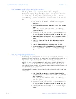
In RSLogix 500, open the
O0-Output
and
I1-Input
force files.
FIGURE A–8: Input Force File
Z
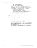
To turn on the Run1 contactor, toggle the O:1/16 bit to
1
. To turn off
Run1, set this bit to
0
.
The status of the Run1 contactor is indicated by the I:1.1/18 bit.
The remote (DeviceNet) control is indicated by the I:1.1/21 bit.
The COS I/O messaging data is available in the I1-Input file, bits I:1.1/24 and onwards.
A.3.8 Explicit Messaging with the LM10 Relay
Explicit messages are stored in the data table of the SLC processor in hexadecimal format.
An M0 copy instruction is used to send the message to the 1747-SDN-scanner module. The
scanner module takes the data and formats it into the proper protocol for transmission on
the DeviceNet network. The destination device (node) receives the message, takes the
appropriate action depending upon the type of command, and formats a reply message
for transmission on the network. The scanner module receives the message that contains
information on the success or failure of the command. The SLC processor uses an M1 copy
instruction to get the message response information from the scanner module. The status
information is placed in the SLC processor data table.
The discussion of Explicit Messaging will be limited to only the elements necessary to allow
this application to function and those that are necessary to provide basic understanding of
the application logic.
Explicit Messaging uses Class, Instance, and Attribute data to build its message structure.
Upon completion of a successful transaction, the logic automatically increments the TXID#
and is ready for the next transaction. Also, the Status data received will be reflected in
Status Word I:s.0 Bit-15. A “1” will be shown for successful message completion. Refer to
the table below for all Status codes as provided by ODVA specification.
Содержание LM10
Страница 6: ...1 IV LM10 MOTOR PROTECTION SYSTEM INSTRUCTION MANUAL TABLE OF CONTENTS ...
Страница 18: ...1 12 LM10 MOTOR PROTECTION SYSTEM INSTRUCTION MANUAL SPECIFICATIONS CHAPTER 1 INTRODUCTION ...
Страница 50: ...4 44 LM10 MOTOR PROTECTION SYSTEM INSTRUCTION MANUAL MOTOR START STOP LOGIC CHAPTER 4 FUNCTIONALITY ...
Страница 70: ...5 64 LM10 MOTOR PROTECTION SYSTEM INSTRUCTION MANUAL SERIAL PORT CHAPTER 5 COMMUNICATIONS ...
Страница 74: ...6 68 LM10 MOTOR PROTECTION SYSTEM INSTRUCTION MANUAL WARRANTY CHAPTER 6 MISCELLANEOUS ...
Страница 102: ...A 28 LM10 MOTOR PROTECTION SYSTEM INSTRUCTION MANUAL LM10 AND ALLEN BRADLEY SLC500 VIA DEVICENET CHAPTERA ...
Страница 106: ...I 4 LM10 MOTOR PROTECTION SYSTEM INSTRUCTION MANUAL INDEX ...


