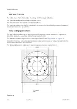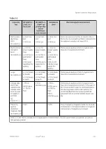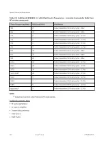
(continued)
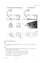
Item
Description
[3]
Middle Plate
[4]
Maximum is 155 mm
[5]
Maximum is 175 mm
The Substructure for Dual Arm suspension is delivered with each system. In the GEHC system catalogue
(Pre-Installation item), its purchase number is S18391MX (MAVIG Purchase number GD60D022).
NOTICE
If the distance between the ceiling and the lower edge of the false ceiling is more
than 610 mm, Long variation of the Substructure for Dual Arm suspension
solution could be proposed by MAVIG.
Substructure mounting
The length of the Substructure for Dual Arm suspension S18391MX can be adapted to any individual
situation (distance between solid ceiling and the lower edge of the false ceiling).
Length calculation and adaptation instruction are provided in the MAVIG substructure assembly
instructions DBF01O0X (where X may be 1 or higher).
The Substructure for Dual Arm suspension must be fastened to the ceiling using six suitable screws.
These screws must be dimensioned according to the conditions of the ceiling and provided by the
customer and must be checked by the structural engineer.
The ceiling plate (
2.1.3 Dimension Drawings on page 37
) must be seated flush to the ceiling in order to
ensure optimum load distribution.
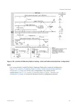
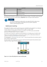
The lower edge of the Substructure for Dual Arm suspension (interface plate [1]) should be the same
height as the lower edge of the false ceiling [2].
Figure 2-63 False ceiling alignment versus interface plate
Equipment Requirements
5750182-1EN 3
Innova
TM
IGS 6
113
Содержание Innova IGS 6
Страница 1: ...InnovaTM IGS 6 Pre Installation Manual 5750182 1EN 3 2017 General Electric Company All rights reserved...
Страница 9: ...Page intentionally left blank...
Страница 23: ...Figure 1 5 Lateral Positioner on shorter type Dolly General Requirements 12 InnovaTM IGS 6 5750182 1EN 3...
Страница 25: ...Omega Table Shipment Figure 1 7 Omega Table Shipment General Requirements 14 InnovaTM IGS 6 5750182 1EN 3...
Страница 27: ...Power Distribution Box PDB CE Figure 1 9 PDB CE Shipment General Requirements 16 InnovaTM IGS 6 5750182 1EN 3...
Страница 29: ...Figure 1 12 Large Display Cabinet on pallet General Requirements 18 InnovaTM IGS 6 5750182 1EN 3...
Страница 54: ...Figure 2 8 Lateral Positioner dimensions Side View Equipment Requirements 5750182 1EN 3 InnovaTM IGS 6 43...
Страница 55: ...Figure 2 9 Lateral Positioner dimensions Top View Equipment Requirements 44 InnovaTM IGS 6 5750182 1EN 3...
Страница 56: ...Figure 2 10 Lateral Positioner dimensions Front View Equipment Requirements 5750182 1EN 3 InnovaTM IGS 6 45...
Страница 57: ...Figure 2 11 Omega V Table dimensions Equipment Requirements 46 InnovaTM IGS 6 5750182 1EN 3...
Страница 59: ...Figure 2 12 Omega Table side clearance CPR access Equipment Requirements 48 InnovaTM IGS 6 5750182 1EN 3...
Страница 60: ...Figure 2 13 Table Head Extender dimensions Equipment Requirements 5750182 1EN 3 InnovaTM IGS 6 49...
Страница 61: ...Figure 2 14 Gas box outlets Omega Table Equipment Requirements 50 InnovaTM IGS 6 5750182 1EN 3...
Страница 69: ...Figure 2 22 C2 Cabinet dimensions Equipment Requirements 58 InnovaTM IGS 6 5750182 1EN 3...
Страница 70: ...Figure 2 23 C1 Frontal Cabinet dimensions Equipment Requirements 5750182 1EN 3 InnovaTM IGS 6 59...
Страница 71: ...Figure 2 24 C1 Lateral Cabinet dimensions Equipment Requirements 60 InnovaTM IGS 6 5750182 1EN 3...
Страница 73: ...Figure 2 26 Detector Conditioner dimensions Equipment Requirements 62 InnovaTM IGS 6 5750182 1EN 3...
Страница 74: ...Figure 2 27 1 kVA Cabinet UPS model 9130 dimensions Equipment Requirements 5750182 1EN 3 InnovaTM IGS 6 63...
Страница 75: ...Figure 2 28 3 kVA LDM UPS model 9130 dimensions Equipment Requirements 64 InnovaTM IGS 6 5750182 1EN 3...
Страница 78: ...Figure 2 31 ECG Acquisition Device Modules dimensions Equipment Requirements 5750182 1EN 3 InnovaTM IGS 6 67...
Страница 79: ...Figure 2 32 Large Display Cabinet dimensions Optional Equipment Requirements 68 InnovaTM IGS 6 5750182 1EN 3...
Страница 100: ...Figure 2 47 Hole location in concrete floor Equipment Requirements 5750182 1EN 3 InnovaTM IGS 6 89...
Страница 108: ...Figure 2 52 Innova Frontal Positioner Floor Mounting Methods 1 2 Equipment Requirements 5750182 1EN 3 InnovaTM IGS 6 97...
Страница 109: ...Figure 2 53 Innova Frontal Positioner Floor Mounting Methods 2 2 Equipment Requirements 98 InnovaTM IGS 6 5750182 1EN 3...
Страница 110: ...Figure 2 54 Inner Base Plate For Above Grade Floor Anchor Kit Equipment Requirements 5750182 1EN 3 InnovaTM IGS 6 99...
Страница 111: ...Figure 2 55 Cable Conduit For On Grade Floor Anchor Kit Equipment Requirements 100 InnovaTM IGS 6 5750182 1EN 3...
Страница 114: ...Figure 2 57 Gantry and table mounting holes Equipment Requirements 5750182 1EN 3 InnovaTM IGS 6 103...
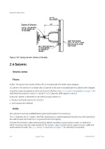
Страница 129: ...Figure 2 1 Center of gravity and seismic support and attachments Equipment Requirements 118 InnovaTM IGS 6 5750182 1EN 3...
Страница 139: ...Page intentionally left blank Special Construction Requirements 128 InnovaTM IGS 6 5750182 1EN 3...
Страница 147: ...Page intentionally left blank Environmental Requirements 136 InnovaTM IGS 6 5750182 1EN 3...
Страница 157: ...Power Distribution Box CE Figure 5 5 PDB CE 50 Hz Electrical Requirements 146 InnovaTM IGS 6 5750182 1EN 3...
Страница 158: ...Figure 5 6 PDB Schematic CE 1 2 Electrical Requirements 5750182 1EN 3 InnovaTM IGS 6 147...
Страница 159: ...Figure 5 7 PDB Schematic CE 2 2 Electrical Requirements 148 InnovaTM IGS 6 5750182 1EN 3...
Страница 160: ...Power Distribution Box UL Figure 5 8 PDB UL 60 Hz US only Electrical Requirements 5750182 1EN 3 InnovaTM IGS 6 149...
Страница 161: ...Figure 5 9 PDB Schematic UL 1 2 Electrical Requirements 150 InnovaTM IGS 6 5750182 1EN 3...
Страница 172: ...Figure 5 15 CABLE GROUP 1 FROM TECHNICAL AREA TO EXAM AREA Electrical Requirements 5750182 1EN 3 InnovaTM IGS 6 161...
Страница 173: ...Figure 5 16 CABLE GROUP 2 FROM TECHNICAL AREA TO CONTROL AREA Electrical Requirements 162 InnovaTM IGS 6 5750182 1EN 3...
Страница 174: ...Figure 5 17 Cable Group Fast Link Option Electrical Requirements 5750182 1EN 3 InnovaTM IGS 6 163...
Страница 175: ...Figure 5 18 CABLE GROUP 3 FROM TECHNICAL AREA TO TECHNICAL AREA Electrical Requirements 164 InnovaTM IGS 6 5750182 1EN 3...
Страница 176: ...Figure 5 19 CABLE GROUP 4 FROM TECHNICAL AREA TO EXAM AREA Electrical Requirements 5750182 1EN 3 InnovaTM IGS 6 165...
Страница 177: ...Figure 5 20 CABLE GROUP 5 FROM TECHNICAL AREA TO EXAM AREA Electrical Requirements 166 InnovaTM IGS 6 5750182 1EN 3...
Страница 194: ...InnovaTM IGS 6...


