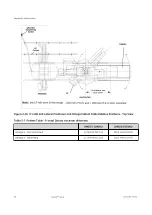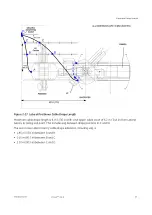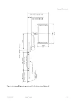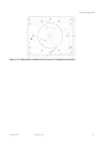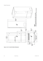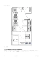
Figure 2-30 Fluoro UPS CE dimensions (Optional)
The UPS cabinet can be positioned against the wall but, in order to improve the ventilation and to make
easier the maintenance operations for UPS and battery, we recommend a minimum distance of 200 mm
(8”) from the wall.
For maintenance operations, a minimum clearance distance of 500 mm (20”) is required for both left and
right sides of the UPS cabinet.
In front of the cabinet, the clear width of the service area to insure electrical safety shall be at least 0.9
m. In cases where 2 cabinets are installed face to face (both sides of the access way), the clear width
shall be at least 1.2 m.
Recommended minimum clearance between ceiling and top of the UPS should be 400 mm (16”) for
proper cooling air exhaust.
NOTE
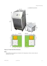
A minimum distance of 2 m (79 in) between X-Ray tube Chiller and Fluoro UPS CE cabinet
is required.
NOTE
A Fire extinguisher (non-water type, ex. CO2) shall be provided and installed by the
customer close to the Fluoro UPS CE cabinet.
Equipment Requirements
66
Innova
TM
IGS 6
5750182-1EN 3
Содержание Innova IGS 6
Страница 1: ...InnovaTM IGS 6 Pre Installation Manual 5750182 1EN 3 2017 General Electric Company All rights reserved...
Страница 9: ...Page intentionally left blank...
Страница 23: ...Figure 1 5 Lateral Positioner on shorter type Dolly General Requirements 12 InnovaTM IGS 6 5750182 1EN 3...
Страница 25: ...Omega Table Shipment Figure 1 7 Omega Table Shipment General Requirements 14 InnovaTM IGS 6 5750182 1EN 3...
Страница 27: ...Power Distribution Box PDB CE Figure 1 9 PDB CE Shipment General Requirements 16 InnovaTM IGS 6 5750182 1EN 3...
Страница 29: ...Figure 1 12 Large Display Cabinet on pallet General Requirements 18 InnovaTM IGS 6 5750182 1EN 3...
Страница 54: ...Figure 2 8 Lateral Positioner dimensions Side View Equipment Requirements 5750182 1EN 3 InnovaTM IGS 6 43...
Страница 55: ...Figure 2 9 Lateral Positioner dimensions Top View Equipment Requirements 44 InnovaTM IGS 6 5750182 1EN 3...
Страница 56: ...Figure 2 10 Lateral Positioner dimensions Front View Equipment Requirements 5750182 1EN 3 InnovaTM IGS 6 45...
Страница 57: ...Figure 2 11 Omega V Table dimensions Equipment Requirements 46 InnovaTM IGS 6 5750182 1EN 3...
Страница 59: ...Figure 2 12 Omega Table side clearance CPR access Equipment Requirements 48 InnovaTM IGS 6 5750182 1EN 3...
Страница 60: ...Figure 2 13 Table Head Extender dimensions Equipment Requirements 5750182 1EN 3 InnovaTM IGS 6 49...
Страница 61: ...Figure 2 14 Gas box outlets Omega Table Equipment Requirements 50 InnovaTM IGS 6 5750182 1EN 3...
Страница 69: ...Figure 2 22 C2 Cabinet dimensions Equipment Requirements 58 InnovaTM IGS 6 5750182 1EN 3...
Страница 70: ...Figure 2 23 C1 Frontal Cabinet dimensions Equipment Requirements 5750182 1EN 3 InnovaTM IGS 6 59...
Страница 71: ...Figure 2 24 C1 Lateral Cabinet dimensions Equipment Requirements 60 InnovaTM IGS 6 5750182 1EN 3...
Страница 73: ...Figure 2 26 Detector Conditioner dimensions Equipment Requirements 62 InnovaTM IGS 6 5750182 1EN 3...
Страница 74: ...Figure 2 27 1 kVA Cabinet UPS model 9130 dimensions Equipment Requirements 5750182 1EN 3 InnovaTM IGS 6 63...
Страница 75: ...Figure 2 28 3 kVA LDM UPS model 9130 dimensions Equipment Requirements 64 InnovaTM IGS 6 5750182 1EN 3...
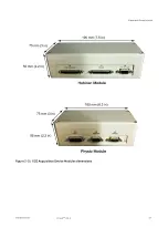
Страница 78: ...Figure 2 31 ECG Acquisition Device Modules dimensions Equipment Requirements 5750182 1EN 3 InnovaTM IGS 6 67...
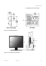
Страница 79: ...Figure 2 32 Large Display Cabinet dimensions Optional Equipment Requirements 68 InnovaTM IGS 6 5750182 1EN 3...
Страница 100: ...Figure 2 47 Hole location in concrete floor Equipment Requirements 5750182 1EN 3 InnovaTM IGS 6 89...
Страница 108: ...Figure 2 52 Innova Frontal Positioner Floor Mounting Methods 1 2 Equipment Requirements 5750182 1EN 3 InnovaTM IGS 6 97...
Страница 109: ...Figure 2 53 Innova Frontal Positioner Floor Mounting Methods 2 2 Equipment Requirements 98 InnovaTM IGS 6 5750182 1EN 3...
Страница 110: ...Figure 2 54 Inner Base Plate For Above Grade Floor Anchor Kit Equipment Requirements 5750182 1EN 3 InnovaTM IGS 6 99...
Страница 111: ...Figure 2 55 Cable Conduit For On Grade Floor Anchor Kit Equipment Requirements 100 InnovaTM IGS 6 5750182 1EN 3...
Страница 114: ...Figure 2 57 Gantry and table mounting holes Equipment Requirements 5750182 1EN 3 InnovaTM IGS 6 103...
Страница 129: ...Figure 2 1 Center of gravity and seismic support and attachments Equipment Requirements 118 InnovaTM IGS 6 5750182 1EN 3...
Страница 139: ...Page intentionally left blank Special Construction Requirements 128 InnovaTM IGS 6 5750182 1EN 3...
Страница 147: ...Page intentionally left blank Environmental Requirements 136 InnovaTM IGS 6 5750182 1EN 3...
Страница 157: ...Power Distribution Box CE Figure 5 5 PDB CE 50 Hz Electrical Requirements 146 InnovaTM IGS 6 5750182 1EN 3...
Страница 158: ...Figure 5 6 PDB Schematic CE 1 2 Electrical Requirements 5750182 1EN 3 InnovaTM IGS 6 147...
Страница 159: ...Figure 5 7 PDB Schematic CE 2 2 Electrical Requirements 148 InnovaTM IGS 6 5750182 1EN 3...
Страница 160: ...Power Distribution Box UL Figure 5 8 PDB UL 60 Hz US only Electrical Requirements 5750182 1EN 3 InnovaTM IGS 6 149...
Страница 161: ...Figure 5 9 PDB Schematic UL 1 2 Electrical Requirements 150 InnovaTM IGS 6 5750182 1EN 3...
Страница 172: ...Figure 5 15 CABLE GROUP 1 FROM TECHNICAL AREA TO EXAM AREA Electrical Requirements 5750182 1EN 3 InnovaTM IGS 6 161...
Страница 173: ...Figure 5 16 CABLE GROUP 2 FROM TECHNICAL AREA TO CONTROL AREA Electrical Requirements 162 InnovaTM IGS 6 5750182 1EN 3...
Страница 174: ...Figure 5 17 Cable Group Fast Link Option Electrical Requirements 5750182 1EN 3 InnovaTM IGS 6 163...
Страница 175: ...Figure 5 18 CABLE GROUP 3 FROM TECHNICAL AREA TO TECHNICAL AREA Electrical Requirements 164 InnovaTM IGS 6 5750182 1EN 3...
Страница 176: ...Figure 5 19 CABLE GROUP 4 FROM TECHNICAL AREA TO EXAM AREA Electrical Requirements 5750182 1EN 3 InnovaTM IGS 6 165...
Страница 177: ...Figure 5 20 CABLE GROUP 5 FROM TECHNICAL AREA TO EXAM AREA Electrical Requirements 166 InnovaTM IGS 6 5750182 1EN 3...
Страница 194: ...InnovaTM IGS 6...

