


continued
HEAT OUTPUT
Stand by
Moderate Use (8
cases / a 10 hour
day)
Typical Use (13
cases / a 10 hour
day)
Maximum Use
(maximum peak
power during ex-
am)
Room
Core System
kW
BTU/hr
kW
BTU/hr
kW
BTU/hr
kW
BTU/hr
Note (3): For UPS 20 kVA option refer to
Note (4): The 2nd optional LD monitor is not necessarily in the control room. It may be installed in the exam room
(outside patient vicinity).
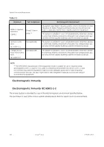
CAUTION
Make sure there is a ventilation air flow, preferably ensured by natural air flow,
otherwise by enforced ventilation, so that hydrogen concentration is below 1%
(according to Standard IEC 62040-1-2).
Fluoro UPS Option
Figure 4-1
The heat produced by the UPS is transferred to the environment by its ventilation. Cooling air enters the
cabinets through the air inlet (grids) located at the bottom and exhausted through the outlet on the roof.
A suitable ventilation or cooling system must be installed to extract the heat from the UPS room.
NOTICE
Do not put anything on the top of the cabinet.
If the UPS is placed on a raised floor, the airflow for UPS cooling should enter from underneath the UPS,
through the appropriate aperture on the raised floor.
If the UPS runs in a dusty environment, we recommend strongly to install filters on the air inlet of the UPS
room. In this case it should be considered that these filters can cause reduced speed at the air inlet.
The size of the air inlet has therefore to be dimensioned accordingly.
Contact your Local Distributor or one of the Service Centre, which will help you to find valuable solutions.
Environmental Requirements
5750182-1EN 3
Innova
TM
IGS 6
133
Содержание Innova IGS 6
Страница 1: ...InnovaTM IGS 6 Pre Installation Manual 5750182 1EN 3 2017 General Electric Company All rights reserved...
Страница 9: ...Page intentionally left blank...
Страница 23: ...Figure 1 5 Lateral Positioner on shorter type Dolly General Requirements 12 InnovaTM IGS 6 5750182 1EN 3...
Страница 25: ...Omega Table Shipment Figure 1 7 Omega Table Shipment General Requirements 14 InnovaTM IGS 6 5750182 1EN 3...
Страница 27: ...Power Distribution Box PDB CE Figure 1 9 PDB CE Shipment General Requirements 16 InnovaTM IGS 6 5750182 1EN 3...
Страница 29: ...Figure 1 12 Large Display Cabinet on pallet General Requirements 18 InnovaTM IGS 6 5750182 1EN 3...
Страница 54: ...Figure 2 8 Lateral Positioner dimensions Side View Equipment Requirements 5750182 1EN 3 InnovaTM IGS 6 43...
Страница 55: ...Figure 2 9 Lateral Positioner dimensions Top View Equipment Requirements 44 InnovaTM IGS 6 5750182 1EN 3...
Страница 56: ...Figure 2 10 Lateral Positioner dimensions Front View Equipment Requirements 5750182 1EN 3 InnovaTM IGS 6 45...
Страница 57: ...Figure 2 11 Omega V Table dimensions Equipment Requirements 46 InnovaTM IGS 6 5750182 1EN 3...
Страница 59: ...Figure 2 12 Omega Table side clearance CPR access Equipment Requirements 48 InnovaTM IGS 6 5750182 1EN 3...
Страница 60: ...Figure 2 13 Table Head Extender dimensions Equipment Requirements 5750182 1EN 3 InnovaTM IGS 6 49...
Страница 61: ...Figure 2 14 Gas box outlets Omega Table Equipment Requirements 50 InnovaTM IGS 6 5750182 1EN 3...
Страница 69: ...Figure 2 22 C2 Cabinet dimensions Equipment Requirements 58 InnovaTM IGS 6 5750182 1EN 3...
Страница 70: ...Figure 2 23 C1 Frontal Cabinet dimensions Equipment Requirements 5750182 1EN 3 InnovaTM IGS 6 59...
Страница 71: ...Figure 2 24 C1 Lateral Cabinet dimensions Equipment Requirements 60 InnovaTM IGS 6 5750182 1EN 3...
Страница 73: ...Figure 2 26 Detector Conditioner dimensions Equipment Requirements 62 InnovaTM IGS 6 5750182 1EN 3...
Страница 74: ...Figure 2 27 1 kVA Cabinet UPS model 9130 dimensions Equipment Requirements 5750182 1EN 3 InnovaTM IGS 6 63...
Страница 75: ...Figure 2 28 3 kVA LDM UPS model 9130 dimensions Equipment Requirements 64 InnovaTM IGS 6 5750182 1EN 3...
Страница 78: ...Figure 2 31 ECG Acquisition Device Modules dimensions Equipment Requirements 5750182 1EN 3 InnovaTM IGS 6 67...
Страница 79: ...Figure 2 32 Large Display Cabinet dimensions Optional Equipment Requirements 68 InnovaTM IGS 6 5750182 1EN 3...
Страница 100: ...Figure 2 47 Hole location in concrete floor Equipment Requirements 5750182 1EN 3 InnovaTM IGS 6 89...
Страница 108: ...Figure 2 52 Innova Frontal Positioner Floor Mounting Methods 1 2 Equipment Requirements 5750182 1EN 3 InnovaTM IGS 6 97...
Страница 109: ...Figure 2 53 Innova Frontal Positioner Floor Mounting Methods 2 2 Equipment Requirements 98 InnovaTM IGS 6 5750182 1EN 3...
Страница 110: ...Figure 2 54 Inner Base Plate For Above Grade Floor Anchor Kit Equipment Requirements 5750182 1EN 3 InnovaTM IGS 6 99...
Страница 111: ...Figure 2 55 Cable Conduit For On Grade Floor Anchor Kit Equipment Requirements 100 InnovaTM IGS 6 5750182 1EN 3...
Страница 114: ...Figure 2 57 Gantry and table mounting holes Equipment Requirements 5750182 1EN 3 InnovaTM IGS 6 103...
Страница 129: ...Figure 2 1 Center of gravity and seismic support and attachments Equipment Requirements 118 InnovaTM IGS 6 5750182 1EN 3...
Страница 139: ...Page intentionally left blank Special Construction Requirements 128 InnovaTM IGS 6 5750182 1EN 3...
Страница 147: ...Page intentionally left blank Environmental Requirements 136 InnovaTM IGS 6 5750182 1EN 3...
Страница 157: ...Power Distribution Box CE Figure 5 5 PDB CE 50 Hz Electrical Requirements 146 InnovaTM IGS 6 5750182 1EN 3...
Страница 158: ...Figure 5 6 PDB Schematic CE 1 2 Electrical Requirements 5750182 1EN 3 InnovaTM IGS 6 147...
Страница 159: ...Figure 5 7 PDB Schematic CE 2 2 Electrical Requirements 148 InnovaTM IGS 6 5750182 1EN 3...
Страница 160: ...Power Distribution Box UL Figure 5 8 PDB UL 60 Hz US only Electrical Requirements 5750182 1EN 3 InnovaTM IGS 6 149...
Страница 161: ...Figure 5 9 PDB Schematic UL 1 2 Electrical Requirements 150 InnovaTM IGS 6 5750182 1EN 3...
Страница 172: ...Figure 5 15 CABLE GROUP 1 FROM TECHNICAL AREA TO EXAM AREA Electrical Requirements 5750182 1EN 3 InnovaTM IGS 6 161...
Страница 173: ...Figure 5 16 CABLE GROUP 2 FROM TECHNICAL AREA TO CONTROL AREA Electrical Requirements 162 InnovaTM IGS 6 5750182 1EN 3...
Страница 174: ...Figure 5 17 Cable Group Fast Link Option Electrical Requirements 5750182 1EN 3 InnovaTM IGS 6 163...
Страница 175: ...Figure 5 18 CABLE GROUP 3 FROM TECHNICAL AREA TO TECHNICAL AREA Electrical Requirements 164 InnovaTM IGS 6 5750182 1EN 3...
Страница 176: ...Figure 5 19 CABLE GROUP 4 FROM TECHNICAL AREA TO EXAM AREA Electrical Requirements 5750182 1EN 3 InnovaTM IGS 6 165...
Страница 177: ...Figure 5 20 CABLE GROUP 5 FROM TECHNICAL AREA TO EXAM AREA Electrical Requirements 166 InnovaTM IGS 6 5750182 1EN 3...
Страница 194: ...InnovaTM IGS 6...


