


Reference
For additional details on ceiling requirements for stationary rails, refer to:
• Direction 46–019639, Advantx (VHLA) XT Stationary Rails Installation and Adjustment.
• Direction 2393190-100, Pre-Installation Manual for LCD Monitor Suspension with 4, 6, or 8 monitors.
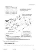
Rail Mounting
Attach stationary rails to structural steel with through-bolts in concrete ceilings. Do not use screw
anchors in direct tension.
Mount stationary rails directly to the ceiling slab or to flush–mounted unistrut or halfen structure. In
higher rooms with false ceiling, mount stationary rails to rigid vertical members hung from ceiling slab.
Securing a supplementary channel to the bottom of the vertical members and mounting the stationary
rails to this channel can greatly reduce the number of vertical members.
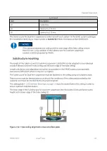
The stationary rail support structure must be leveled before installation can begin. Do not assume that
any support structure is level within specified tolerances, particularly after removing suspensions from
an existing room.
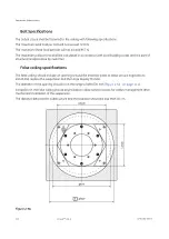
Bolt Specifications
• The maximum load per bolt will not exceed 350 lbs (1557 N).
• Each bolt must not “pull out” or otherwise fail under a vertically downward dead load of 1400 lbs (6228
N).
Rails selection
Monitor suspension rails in different lengths can be selected. Please refer to the GTC or contact the GE
representative.
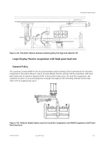
Third Party Monitor suspension (option)
Attention must be paid to the height of suspended elements of the third party suspension, collision must
be avoided with the gantry.
Equipment Requirements
110
Innova
TM
IGS 6
5750182-1EN 3
Содержание Innova IGS 6
Страница 1: ...InnovaTM IGS 6 Pre Installation Manual 5750182 1EN 3 2017 General Electric Company All rights reserved...
Страница 9: ...Page intentionally left blank...
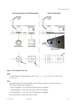
Страница 23: ...Figure 1 5 Lateral Positioner on shorter type Dolly General Requirements 12 InnovaTM IGS 6 5750182 1EN 3...
Страница 25: ...Omega Table Shipment Figure 1 7 Omega Table Shipment General Requirements 14 InnovaTM IGS 6 5750182 1EN 3...
Страница 27: ...Power Distribution Box PDB CE Figure 1 9 PDB CE Shipment General Requirements 16 InnovaTM IGS 6 5750182 1EN 3...
Страница 29: ...Figure 1 12 Large Display Cabinet on pallet General Requirements 18 InnovaTM IGS 6 5750182 1EN 3...
Страница 54: ...Figure 2 8 Lateral Positioner dimensions Side View Equipment Requirements 5750182 1EN 3 InnovaTM IGS 6 43...
Страница 55: ...Figure 2 9 Lateral Positioner dimensions Top View Equipment Requirements 44 InnovaTM IGS 6 5750182 1EN 3...
Страница 56: ...Figure 2 10 Lateral Positioner dimensions Front View Equipment Requirements 5750182 1EN 3 InnovaTM IGS 6 45...
Страница 57: ...Figure 2 11 Omega V Table dimensions Equipment Requirements 46 InnovaTM IGS 6 5750182 1EN 3...
Страница 59: ...Figure 2 12 Omega Table side clearance CPR access Equipment Requirements 48 InnovaTM IGS 6 5750182 1EN 3...
Страница 60: ...Figure 2 13 Table Head Extender dimensions Equipment Requirements 5750182 1EN 3 InnovaTM IGS 6 49...
Страница 61: ...Figure 2 14 Gas box outlets Omega Table Equipment Requirements 50 InnovaTM IGS 6 5750182 1EN 3...
Страница 69: ...Figure 2 22 C2 Cabinet dimensions Equipment Requirements 58 InnovaTM IGS 6 5750182 1EN 3...
Страница 70: ...Figure 2 23 C1 Frontal Cabinet dimensions Equipment Requirements 5750182 1EN 3 InnovaTM IGS 6 59...
Страница 71: ...Figure 2 24 C1 Lateral Cabinet dimensions Equipment Requirements 60 InnovaTM IGS 6 5750182 1EN 3...
Страница 73: ...Figure 2 26 Detector Conditioner dimensions Equipment Requirements 62 InnovaTM IGS 6 5750182 1EN 3...
Страница 74: ...Figure 2 27 1 kVA Cabinet UPS model 9130 dimensions Equipment Requirements 5750182 1EN 3 InnovaTM IGS 6 63...
Страница 75: ...Figure 2 28 3 kVA LDM UPS model 9130 dimensions Equipment Requirements 64 InnovaTM IGS 6 5750182 1EN 3...
Страница 78: ...Figure 2 31 ECG Acquisition Device Modules dimensions Equipment Requirements 5750182 1EN 3 InnovaTM IGS 6 67...
Страница 79: ...Figure 2 32 Large Display Cabinet dimensions Optional Equipment Requirements 68 InnovaTM IGS 6 5750182 1EN 3...
Страница 100: ...Figure 2 47 Hole location in concrete floor Equipment Requirements 5750182 1EN 3 InnovaTM IGS 6 89...
Страница 108: ...Figure 2 52 Innova Frontal Positioner Floor Mounting Methods 1 2 Equipment Requirements 5750182 1EN 3 InnovaTM IGS 6 97...
Страница 109: ...Figure 2 53 Innova Frontal Positioner Floor Mounting Methods 2 2 Equipment Requirements 98 InnovaTM IGS 6 5750182 1EN 3...
Страница 110: ...Figure 2 54 Inner Base Plate For Above Grade Floor Anchor Kit Equipment Requirements 5750182 1EN 3 InnovaTM IGS 6 99...
Страница 111: ...Figure 2 55 Cable Conduit For On Grade Floor Anchor Kit Equipment Requirements 100 InnovaTM IGS 6 5750182 1EN 3...
Страница 114: ...Figure 2 57 Gantry and table mounting holes Equipment Requirements 5750182 1EN 3 InnovaTM IGS 6 103...
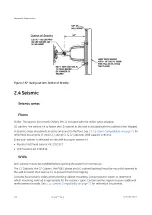
Страница 129: ...Figure 2 1 Center of gravity and seismic support and attachments Equipment Requirements 118 InnovaTM IGS 6 5750182 1EN 3...
Страница 139: ...Page intentionally left blank Special Construction Requirements 128 InnovaTM IGS 6 5750182 1EN 3...
Страница 147: ...Page intentionally left blank Environmental Requirements 136 InnovaTM IGS 6 5750182 1EN 3...
Страница 157: ...Power Distribution Box CE Figure 5 5 PDB CE 50 Hz Electrical Requirements 146 InnovaTM IGS 6 5750182 1EN 3...
Страница 158: ...Figure 5 6 PDB Schematic CE 1 2 Electrical Requirements 5750182 1EN 3 InnovaTM IGS 6 147...
Страница 159: ...Figure 5 7 PDB Schematic CE 2 2 Electrical Requirements 148 InnovaTM IGS 6 5750182 1EN 3...
Страница 160: ...Power Distribution Box UL Figure 5 8 PDB UL 60 Hz US only Electrical Requirements 5750182 1EN 3 InnovaTM IGS 6 149...
Страница 161: ...Figure 5 9 PDB Schematic UL 1 2 Electrical Requirements 150 InnovaTM IGS 6 5750182 1EN 3...
Страница 172: ...Figure 5 15 CABLE GROUP 1 FROM TECHNICAL AREA TO EXAM AREA Electrical Requirements 5750182 1EN 3 InnovaTM IGS 6 161...
Страница 173: ...Figure 5 16 CABLE GROUP 2 FROM TECHNICAL AREA TO CONTROL AREA Electrical Requirements 162 InnovaTM IGS 6 5750182 1EN 3...
Страница 174: ...Figure 5 17 Cable Group Fast Link Option Electrical Requirements 5750182 1EN 3 InnovaTM IGS 6 163...
Страница 175: ...Figure 5 18 CABLE GROUP 3 FROM TECHNICAL AREA TO TECHNICAL AREA Electrical Requirements 164 InnovaTM IGS 6 5750182 1EN 3...
Страница 176: ...Figure 5 19 CABLE GROUP 4 FROM TECHNICAL AREA TO EXAM AREA Electrical Requirements 5750182 1EN 3 InnovaTM IGS 6 165...
Страница 177: ...Figure 5 20 CABLE GROUP 5 FROM TECHNICAL AREA TO EXAM AREA Electrical Requirements 166 InnovaTM IGS 6 5750182 1EN 3...
Страница 194: ...InnovaTM IGS 6...


