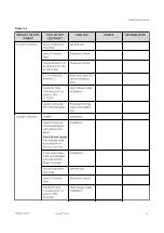
Storage and transport – Relative Humidity and Temperature continued
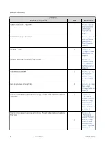
SUB-SYSTEM COMPONENTS
RELATIVE HUMIDITY (NON-
CONDENSING) (see NOTE (2))
TEMPERATURE
MIN
MAX
MIN
MAX
Footswitch
10%
100%
-20°C -4°F
+60°C +140°F
Monitor LCD Eizo
5%
95%
-20°C -4°F
+60°C +140°F
Monitor LDM
10%
90%
-20°C -4°F
+55°C +131°F
Cabinets C1 Frt, C1 Lat, C2
10%
100%
-40°C -40°F
+70°C +158°F
UPS 3 kVA, 1 kVA
5%
90%
-20°C -4°F
+40°C +104°F
Power Distribution Box (PDB) CE
5%
95%
-30°C -22°F
+70°C +158°F
Power Distribution Box (PDB) UL
10%
95%
-30°C -22°F
+70°C +158°F
UL Fluoro UPS cabinet (*)
0%
95%
-20°C -4°F
+50°C +122°F
CE Fluoro UPS cabinet (*)
0%
95%
-20°C -4°F
+50°C +122°F
LDM cabinet LD core
5%
95%
-40°C -40°F
+70°C +158°F
Detector conditioner
5%
95%
-40°C -40°F
+70°C +158°F
Tube chiller Coolix 4100
10%
100%
-40°C -40°F
+70°C +158°F
VCIM
5%
95%
-40°C -40°F
+70°C +158°F
Digital detector
Refer to NOTE (1) below
NOTE
(1): The detector should be stored at 10 to 40 °C (50 to 104 °F) and less than or equal to
90% RH in the plastic wrapped shipping box. (This should include two bags of desiccant as
well). The lowest temperature (e.g. 10 ºC (50 °F)) and humidity is preferable. If they are to be
stored outside of their shipping box or in the inner shipping box without plastic wrapping
they should be stored at 20 °C (68 °F) or less and 30% RH or less. In terms of
transportation, do not expose to temperatures below –20 ºC (–4 °F) in its shipping box for
more than 15 hours. The detector will reach the ambient temperature after 20 to 25 hours.
The detector should not be allowed to reach temperatures less than –10 ºC (14 °F) or
irreparable damage to the detectors scintillator will occur. Care must be taken when
removing a detector from a shipping box. If the detector has been subject to cold
temperatures for an extended period the detector in the box should be allowed to sit in
the plastic wrapped box to reach room temperature. This will prevent condensation from
occurring. Condensation on the detector can cause irreparable damage to the electronics.
Storage 10 to 40 ºC (50 to 104 °F); 10 to 90 % RH, 250 day storage transportation –20 to
+60 ºC (–4 to 140 °F) and 10 to 80% RH. The Detector Conditioner is shipped within GE
Healthcare packaging.
General Requirements
26
Innova
TM
IGS 6
5750182-1EN 3
Содержание Innova IGS 6
Страница 1: ...InnovaTM IGS 6 Pre Installation Manual 5750182 1EN 3 2017 General Electric Company All rights reserved...
Страница 9: ...Page intentionally left blank...
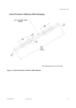
Страница 23: ...Figure 1 5 Lateral Positioner on shorter type Dolly General Requirements 12 InnovaTM IGS 6 5750182 1EN 3...
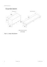
Страница 25: ...Omega Table Shipment Figure 1 7 Omega Table Shipment General Requirements 14 InnovaTM IGS 6 5750182 1EN 3...
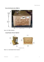
Страница 27: ...Power Distribution Box PDB CE Figure 1 9 PDB CE Shipment General Requirements 16 InnovaTM IGS 6 5750182 1EN 3...
Страница 29: ...Figure 1 12 Large Display Cabinet on pallet General Requirements 18 InnovaTM IGS 6 5750182 1EN 3...
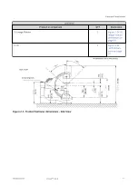
Страница 54: ...Figure 2 8 Lateral Positioner dimensions Side View Equipment Requirements 5750182 1EN 3 InnovaTM IGS 6 43...
Страница 55: ...Figure 2 9 Lateral Positioner dimensions Top View Equipment Requirements 44 InnovaTM IGS 6 5750182 1EN 3...
Страница 56: ...Figure 2 10 Lateral Positioner dimensions Front View Equipment Requirements 5750182 1EN 3 InnovaTM IGS 6 45...
Страница 57: ...Figure 2 11 Omega V Table dimensions Equipment Requirements 46 InnovaTM IGS 6 5750182 1EN 3...
Страница 59: ...Figure 2 12 Omega Table side clearance CPR access Equipment Requirements 48 InnovaTM IGS 6 5750182 1EN 3...
Страница 60: ...Figure 2 13 Table Head Extender dimensions Equipment Requirements 5750182 1EN 3 InnovaTM IGS 6 49...
Страница 61: ...Figure 2 14 Gas box outlets Omega Table Equipment Requirements 50 InnovaTM IGS 6 5750182 1EN 3...
Страница 69: ...Figure 2 22 C2 Cabinet dimensions Equipment Requirements 58 InnovaTM IGS 6 5750182 1EN 3...
Страница 70: ...Figure 2 23 C1 Frontal Cabinet dimensions Equipment Requirements 5750182 1EN 3 InnovaTM IGS 6 59...
Страница 71: ...Figure 2 24 C1 Lateral Cabinet dimensions Equipment Requirements 60 InnovaTM IGS 6 5750182 1EN 3...
Страница 73: ...Figure 2 26 Detector Conditioner dimensions Equipment Requirements 62 InnovaTM IGS 6 5750182 1EN 3...
Страница 74: ...Figure 2 27 1 kVA Cabinet UPS model 9130 dimensions Equipment Requirements 5750182 1EN 3 InnovaTM IGS 6 63...
Страница 75: ...Figure 2 28 3 kVA LDM UPS model 9130 dimensions Equipment Requirements 64 InnovaTM IGS 6 5750182 1EN 3...
Страница 78: ...Figure 2 31 ECG Acquisition Device Modules dimensions Equipment Requirements 5750182 1EN 3 InnovaTM IGS 6 67...
Страница 79: ...Figure 2 32 Large Display Cabinet dimensions Optional Equipment Requirements 68 InnovaTM IGS 6 5750182 1EN 3...
Страница 100: ...Figure 2 47 Hole location in concrete floor Equipment Requirements 5750182 1EN 3 InnovaTM IGS 6 89...
Страница 108: ...Figure 2 52 Innova Frontal Positioner Floor Mounting Methods 1 2 Equipment Requirements 5750182 1EN 3 InnovaTM IGS 6 97...
Страница 109: ...Figure 2 53 Innova Frontal Positioner Floor Mounting Methods 2 2 Equipment Requirements 98 InnovaTM IGS 6 5750182 1EN 3...
Страница 110: ...Figure 2 54 Inner Base Plate For Above Grade Floor Anchor Kit Equipment Requirements 5750182 1EN 3 InnovaTM IGS 6 99...
Страница 111: ...Figure 2 55 Cable Conduit For On Grade Floor Anchor Kit Equipment Requirements 100 InnovaTM IGS 6 5750182 1EN 3...
Страница 114: ...Figure 2 57 Gantry and table mounting holes Equipment Requirements 5750182 1EN 3 InnovaTM IGS 6 103...
Страница 129: ...Figure 2 1 Center of gravity and seismic support and attachments Equipment Requirements 118 InnovaTM IGS 6 5750182 1EN 3...
Страница 139: ...Page intentionally left blank Special Construction Requirements 128 InnovaTM IGS 6 5750182 1EN 3...
Страница 147: ...Page intentionally left blank Environmental Requirements 136 InnovaTM IGS 6 5750182 1EN 3...
Страница 157: ...Power Distribution Box CE Figure 5 5 PDB CE 50 Hz Electrical Requirements 146 InnovaTM IGS 6 5750182 1EN 3...
Страница 158: ...Figure 5 6 PDB Schematic CE 1 2 Electrical Requirements 5750182 1EN 3 InnovaTM IGS 6 147...
Страница 159: ...Figure 5 7 PDB Schematic CE 2 2 Electrical Requirements 148 InnovaTM IGS 6 5750182 1EN 3...
Страница 160: ...Power Distribution Box UL Figure 5 8 PDB UL 60 Hz US only Electrical Requirements 5750182 1EN 3 InnovaTM IGS 6 149...
Страница 161: ...Figure 5 9 PDB Schematic UL 1 2 Electrical Requirements 150 InnovaTM IGS 6 5750182 1EN 3...
Страница 172: ...Figure 5 15 CABLE GROUP 1 FROM TECHNICAL AREA TO EXAM AREA Electrical Requirements 5750182 1EN 3 InnovaTM IGS 6 161...
Страница 173: ...Figure 5 16 CABLE GROUP 2 FROM TECHNICAL AREA TO CONTROL AREA Electrical Requirements 162 InnovaTM IGS 6 5750182 1EN 3...
Страница 174: ...Figure 5 17 Cable Group Fast Link Option Electrical Requirements 5750182 1EN 3 InnovaTM IGS 6 163...
Страница 175: ...Figure 5 18 CABLE GROUP 3 FROM TECHNICAL AREA TO TECHNICAL AREA Electrical Requirements 164 InnovaTM IGS 6 5750182 1EN 3...
Страница 176: ...Figure 5 19 CABLE GROUP 4 FROM TECHNICAL AREA TO EXAM AREA Electrical Requirements 5750182 1EN 3 InnovaTM IGS 6 165...
Страница 177: ...Figure 5 20 CABLE GROUP 5 FROM TECHNICAL AREA TO EXAM AREA Electrical Requirements 166 InnovaTM IGS 6 5750182 1EN 3...
Страница 194: ...InnovaTM IGS 6...


