


User Manual
Chapter 5 Capturing Images and Videos
49
Steering the Probe
Guiding the Insertion Tube Into the Inspection Area
With the desired optical tip installed, guide the insertion tube into the inspection area.
Use your hands to push the tube until it reaches an area you want to inspect.
Twist the insertion tube gently to bring the desired scene into view.
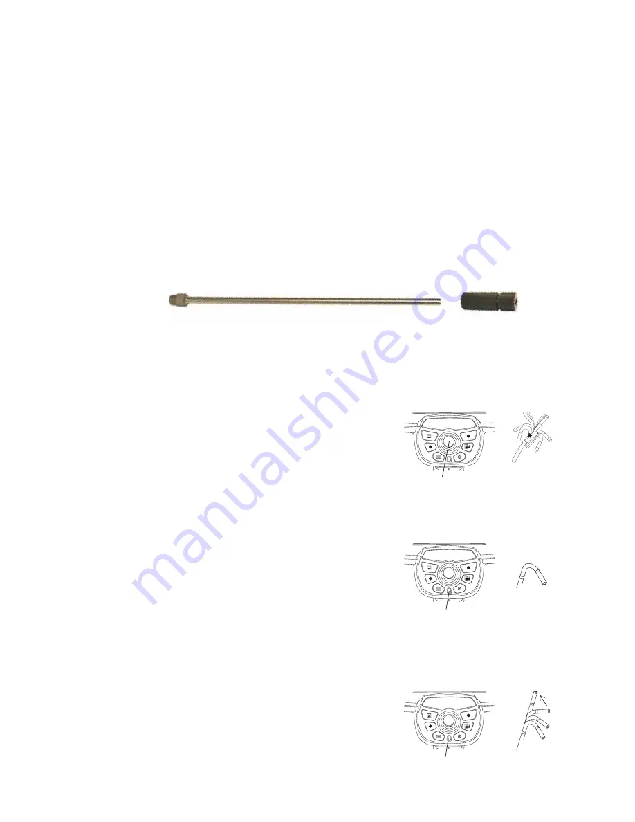
Accessories are available to make it easier to maneuver the tube:
•
Rigidizers, long thin pipes that keep the tube straight as you insert it, are available in
different lengths.
•
A gripper is a cylindrical handle that slides over the insertion tube to make it easier to
control. Grippers are threaded to connect to rigidizers and to access port couplers.
Aiming the Camera
A live image is the image that the camera “sees” in real time. When you are viewing a live
image, you can aim the camera by controlling the bending neck in various ways.
To Articulate the Bending Neck
While viewing a live image, move the joystick toward
the feature you want to see. The bending neck
articulates so that the probe tip moves in that same
direction.
To Hold the Bending Neck in Place
(Steer-and-Stay Mode)
Press the button just below the joystick. Press quickly;
do not hold. The letters
SS
appear, indicating
Steer-and-Stay™ mode.
In this mode, the bending neck holds its position even
when you let go of the joystick. If you move the
joystick while in Steer-and-Stay mode, the bending
neck articulates slowly. When you stop moving the
joystick, the bending neck stays in the new position.
To exit Steer-and-Stay mode, press the button again.
The letters
SS
disappear.
To Straighten the Bending Neck
(HOME)
Press and hold the button just below the joystick.
The bending neck straightens for safe withdrawal and
storage of the insertion tube.
Gripper
Rigidizer
Move the joystick.
Everest XLG3
360
°
All-Way
®
articulation
Press this button.
Everest XLG3
Steer-and-Stay
Hold this button.
Everest XLG3
Home
Содержание Everest XLG3 VideoProbe
Страница 4: ...iv GE Inspection Technologies XLG3 VideoProbe System ...
Страница 8: ...viii GE Inspection Technologies XLG3 VideoProbe System ...
Страница 34: ...26 Chapter 2 Safe Powering and Grounding GE Inspection Technologies XLG3 VideoProbe System ...
Страница 46: ...38 Chapter 3 Setting Up and Putting Away the System GE Inspection Technologies XLG3 VideoProbe System ...
Страница 54: ...46 Chapter 4 Setting Up the Software GE Inspection Technologies XLG3 VideoProbe System ...
Страница 134: ...126 Chapter 8 Maintenance GE Inspection Technologies XLG3 VideoProbe System ...
Страница 138: ...130 Chapter 9 Troubleshooting GE Inspection Technologies XLG3 VideoProbe System ...
Страница 142: ...134 Appendix A Specifications GE Inspection Technologies XLG3 VideoProbe System ...
Страница 146: ...138 Appendix C Chemical Compatibility GE Inspection Technologies XLG3 VideoProbe System ...
Страница 148: ...140 Appendix D Warranty GE Inspection Technologies XLG3 VideoProbe System ...
Страница 166: ...158 Index GE Inspection Technologies XLG3 VideoProbe System ...


