CHAPTER 4: INTERFACES
FRONT PANEL INTERFACE
B30 BUS DIFFERENTIAL SYSTEM – INSTRUCTION MANUAL
4-19
4
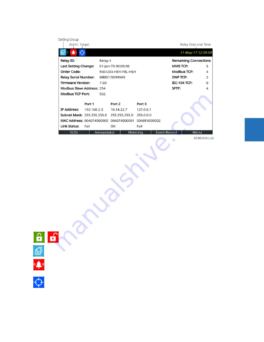
Figure 4-23: Home page example with default content (product information)
There are multiple ways to navigate pages, by using the pushbuttons and the menu hierarchy. The menu hierarchy is
similar to the other front panels whereby you select a submenu using Up and Down arrow pushbuttons, and press the
ENTER
or Right pushbutton. On setting pages, opening a setting for editing is done by highlighting the setting using Up and
Down pushbuttons, and pressing the
ENTER
or Right pushbutton.
Home page
Press the
Home
pushbutton to display the root page no matter the state. Any edit, control, or password entry sessions are
cancelled. The header shows several relay/system status icons. The default content of the home page is the product
information page and can be user-configured to show the content of any single-line diagram page, annunciator page,
metering page, or event records page for example. The Tab pushbuttons on the bottom row each navigate to their page.
The home page displays for a user-configured time period, then scrolls through user-configured pages, a feature referred
to as rolling.
Holding the
Home
pushbutton for one second displays the product information page. The Home page also can display
when settings are saved.
Configure the home page in the software under
Settings > Product Setup > Graphical Panel > Home Page
. The menu
does not display when there is no graphical front panel.
Security indicator, showing how many people are logged in, including local and remote users. The lock is red when
one or more users are logged in and other otherwise green.
When no users are logged in because login is not required, an icon does not display.
Identifies the active setting group number (not shown)
Displays when an abnormal annunciator alarm is present. Navigate to the Annunciator for details. When there
are no such alarms, the icon does not display.
Even when you acknowledge/reset an alarm, the icon displays as long as the condition remains. For example, a
breaker trouble alarm displays, you acknowledge it, but the icon remains because the breaker trouble remains.
Active targets symbol, where targets are error messages.
View error messages by pressing the
Menu
Tab pushbutton, then accessing the
TARGETS
menu. Pressing the
RESET
button clears those messages that can be.
Содержание b30
Страница 10: ...x B30 BUS DIFFERENTIAL SYSTEM INSTRUCTION MANUAL TABLE OF CONTENTS ...
Страница 14: ...1 4 B30 BUS DIFFERENTIAL SYSTEM INSTRUCTION MANUAL FOR FURTHER ASSISTANCE CHAPTER 1 INTRODUCTION 1 ...
Страница 50: ...2 36 B30 BUS DIFFERENTIAL SYSTEM INSTRUCTION MANUAL SPECIFICATIONS CHAPTER 2 PRODUCT DESCRIPTION 2 ...
Страница 208: ...4 86 B30 BUS DIFFERENTIAL SYSTEM INSTRUCTION MANUAL FLEXLOGIC DESIGN USING ENGINEER CHAPTER 4 INTERFACES 4 ...
Страница 441: ...CHAPTER 5 SETTINGS CONTROL ELEMENTS B30 BUS DIFFERENTIAL SYSTEM INSTRUCTION MANUAL 5 233 5 Figure 5 123 Time out mode ...
Страница 486: ...5 278 B30 BUS DIFFERENTIAL SYSTEM INSTRUCTION MANUAL TESTING CHAPTER 5 SETTINGS 5 ...
Страница 514: ...6 28 B30 BUS DIFFERENTIAL SYSTEM INSTRUCTION MANUAL PRODUCT INFORMATION CHAPTER 6 ACTUAL VALUES 6 ...
Страница 528: ...7 14 B30 BUS DIFFERENTIAL SYSTEM INSTRUCTION MANUAL TARGETS MENU CHAPTER 7 COMMANDS AND TARGETS 7 ...
Страница 554: ...9 14 B30 BUS DIFFERENTIAL SYSTEM INSTRUCTION MANUAL OUTPUT LOGIC AND EXAMPLES CHAPTER 9 THEORY OF OPERATION 9 ...
Страница 600: ...A 16 B30 BUS DIFFERENTIAL SYSTEM INSTRUCTION MANUAL FLEXANALOG ITEMS APPENDIX A FLEXANALOG OPERANDS A ...
Страница 608: ...C 6 B30 BUS DIFFERENTIAL SYSTEM INSTRUCTION MANUAL COMMAND LINE INTERFACE APPENDIX C COMMAND LINE INTERFACE C ...
Страница 616: ...iv B30 BUS DIFFERENTIAL SYSTEM INSTRUCTION MANUAL ABBREVIATIONS ...
Страница 632: ...xvi B30 BUS DIFFERENTIAL SYSTEM INSTRUCTION MANUAL INDEX ...


