


4-6
B30 BUS DIFFERENTIAL SYSTEM – INSTRUCTION MANUAL
ENERVISTA SOFTWARE INTERFACE
CHAPTER 4: INTERFACES
4
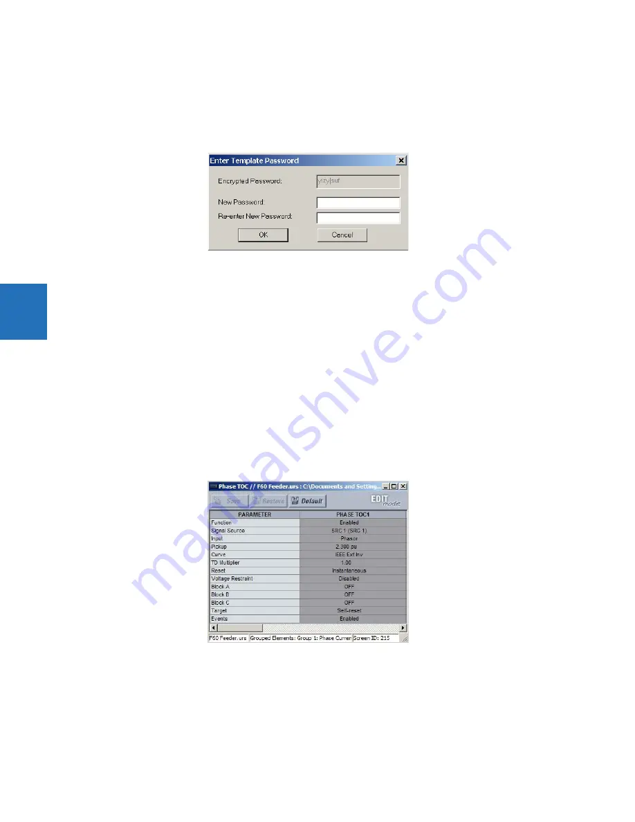
Alternatively, the settings template can be applied to online settings, as follows.
1.
Locate the device in the Online Window area of the EnerVista UR Setup software.
2.
Right-click the device and select the
Template Mode > Create Template
option. The software prompts for a template
password. This password is required to use the template feature and must be at least four characters in length.
Figure 4-3: Entering a settings file password
3.
Enter and re-enter the new password, then click
OK
to continue.
The online settings template is now enabled. The device is now in template editing mode.
4.1.7.2 Edit the settings template
The settings template editing feature allows the user to specify which settings are available for viewing and modification in
EnerVista UR Setup. By default, all settings except the FlexLogic equation editor settings are locked.
1.
With the template already enabled, locate the device or settings file in the Online or Offline Window area in the
software.
2.
Right-click the device or file and select the
Template Mode > Edit Template
option to verify or place the device in
template editing mode (check mark beside option). If prompted, enter the template password then click
OK
.
3.
Open the relevant settings window that contains settings to be specified as viewable.
By default, all settings are specified as locked and displayed against a grey background. The icon on the upper right of
the settings window indicates that the EnerVista software is in
EDIT mode
. The following example shows the phase
time overcurrent settings window in edit mode.
Figure 4-4: Settings template with all settings specified as locked
4.
Specify the settings to make viewable by clicking them.
A setting available to view displays with a yellow background.
Содержание b30
Страница 10: ...x B30 BUS DIFFERENTIAL SYSTEM INSTRUCTION MANUAL TABLE OF CONTENTS ...
Страница 14: ...1 4 B30 BUS DIFFERENTIAL SYSTEM INSTRUCTION MANUAL FOR FURTHER ASSISTANCE CHAPTER 1 INTRODUCTION 1 ...
Страница 50: ...2 36 B30 BUS DIFFERENTIAL SYSTEM INSTRUCTION MANUAL SPECIFICATIONS CHAPTER 2 PRODUCT DESCRIPTION 2 ...
Страница 208: ...4 86 B30 BUS DIFFERENTIAL SYSTEM INSTRUCTION MANUAL FLEXLOGIC DESIGN USING ENGINEER CHAPTER 4 INTERFACES 4 ...
Страница 441: ...CHAPTER 5 SETTINGS CONTROL ELEMENTS B30 BUS DIFFERENTIAL SYSTEM INSTRUCTION MANUAL 5 233 5 Figure 5 123 Time out mode ...
Страница 486: ...5 278 B30 BUS DIFFERENTIAL SYSTEM INSTRUCTION MANUAL TESTING CHAPTER 5 SETTINGS 5 ...
Страница 514: ...6 28 B30 BUS DIFFERENTIAL SYSTEM INSTRUCTION MANUAL PRODUCT INFORMATION CHAPTER 6 ACTUAL VALUES 6 ...
Страница 528: ...7 14 B30 BUS DIFFERENTIAL SYSTEM INSTRUCTION MANUAL TARGETS MENU CHAPTER 7 COMMANDS AND TARGETS 7 ...
Страница 554: ...9 14 B30 BUS DIFFERENTIAL SYSTEM INSTRUCTION MANUAL OUTPUT LOGIC AND EXAMPLES CHAPTER 9 THEORY OF OPERATION 9 ...
Страница 600: ...A 16 B30 BUS DIFFERENTIAL SYSTEM INSTRUCTION MANUAL FLEXANALOG ITEMS APPENDIX A FLEXANALOG OPERANDS A ...
Страница 608: ...C 6 B30 BUS DIFFERENTIAL SYSTEM INSTRUCTION MANUAL COMMAND LINE INTERFACE APPENDIX C COMMAND LINE INTERFACE C ...
Страница 616: ...iv B30 BUS DIFFERENTIAL SYSTEM INSTRUCTION MANUAL ABBREVIATIONS ...
Страница 632: ...xvi B30 BUS DIFFERENTIAL SYSTEM INSTRUCTION MANUAL INDEX ...


