5-146
B30 BUS DIFFERENTIAL SYSTEM – INSTRUCTION MANUAL
SYSTEM SETUP
CHAPTER 5: SETTINGS
5
5.5.3.2 AC input actual values
The calculated parameters associated with the configured voltage and current inputs are displayed in the current and
voltage sections of actual values. Only the phasor quantities associated with the actual AC physical input channels display
here. All parameters contained within a configured source are displayed in the sources section of the actual values.
5.5.3.3 Disturbance detectors (internal)
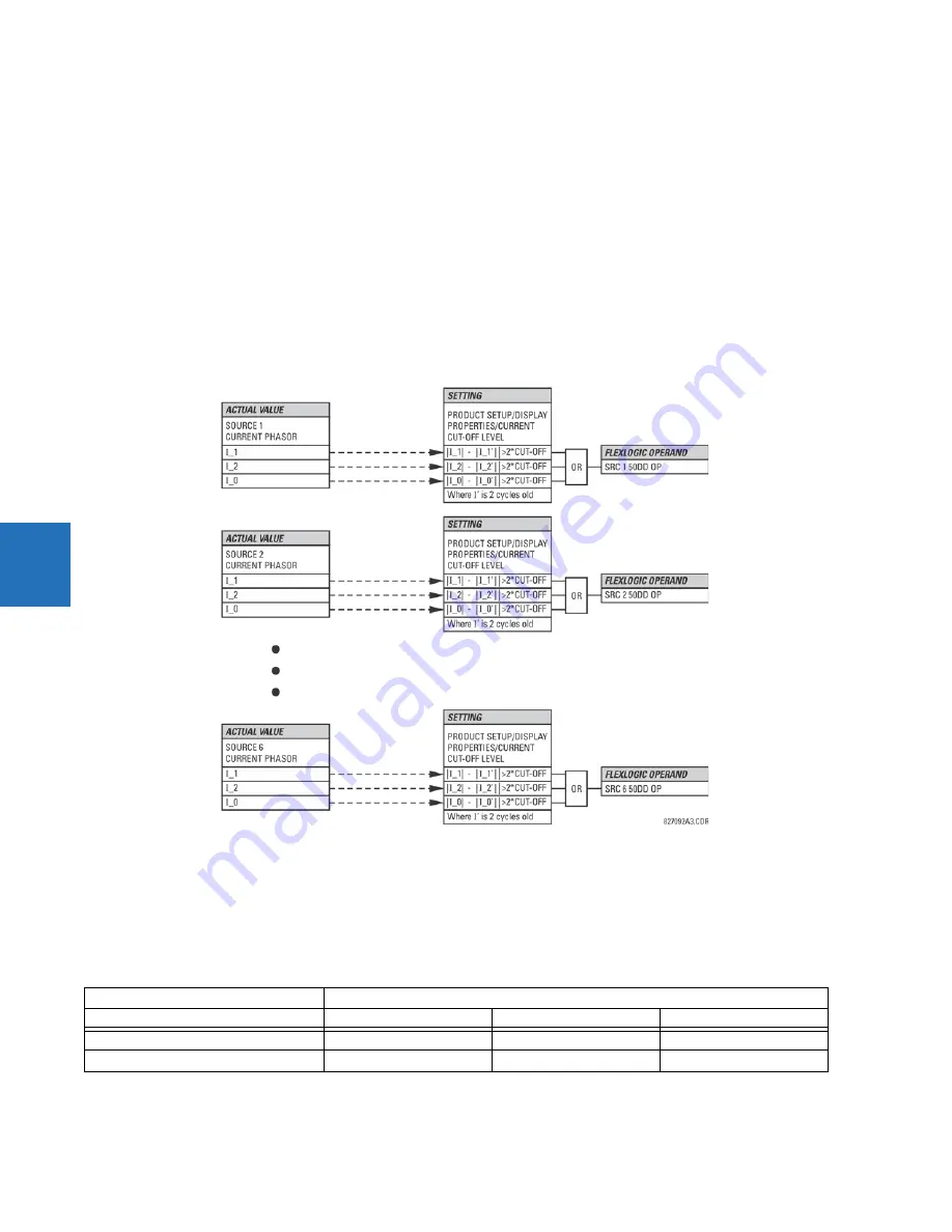
The disturbance detector (ANSI 50DD) element is a sensitive current disturbance detector that detects any disturbance on
the protected system. The 50DD function is used directly in some elements in the relay, for example VT Fuse Failure
detector or Fault Report. It can also be used to supervise current-based elements to prevent maloperation as a result of
the wrong settings or external CT wiring problem. A disturbance detector is provided for each source.
The 50DD function responds to the changes in magnitude of the sequence currents. The disturbance detector logic is as
follows.
Figure 5-67: Disturbance detector logic
The disturbance detector responds to the change in currents of twice the current cut-off level. The default cut-off threshold
is 0.02 pu; thus by default the disturbance detector responds to a change of 0.04 pu. The metering sensitivity setting
(
PRODUCT SETUP
DISPLAY PROPERTIES
CURRENT CUT-OFF LEVEL
) controls the sensitivity of the disturbance detector
accordingly.
5.5.3.4 Example for use of sources
An example of the use of sources is shown in the following figure. A relay can have the following hardware configuration:
Increasing slot position letter -->
UR
CT/VT module 1
CT/VT module 2
CT/VT module 3
B30, B90, C70, F35, N60, T35
8 CTs
4 CTs, 4 VTs
4 CTs, 4 VTs
C60, D60, G30, G60, L30, L90, M60, T60
CTs
VTs
not applicable
Содержание b30
Страница 10: ...x B30 BUS DIFFERENTIAL SYSTEM INSTRUCTION MANUAL TABLE OF CONTENTS ...
Страница 14: ...1 4 B30 BUS DIFFERENTIAL SYSTEM INSTRUCTION MANUAL FOR FURTHER ASSISTANCE CHAPTER 1 INTRODUCTION 1 ...
Страница 50: ...2 36 B30 BUS DIFFERENTIAL SYSTEM INSTRUCTION MANUAL SPECIFICATIONS CHAPTER 2 PRODUCT DESCRIPTION 2 ...
Страница 208: ...4 86 B30 BUS DIFFERENTIAL SYSTEM INSTRUCTION MANUAL FLEXLOGIC DESIGN USING ENGINEER CHAPTER 4 INTERFACES 4 ...
Страница 441: ...CHAPTER 5 SETTINGS CONTROL ELEMENTS B30 BUS DIFFERENTIAL SYSTEM INSTRUCTION MANUAL 5 233 5 Figure 5 123 Time out mode ...
Страница 486: ...5 278 B30 BUS DIFFERENTIAL SYSTEM INSTRUCTION MANUAL TESTING CHAPTER 5 SETTINGS 5 ...
Страница 514: ...6 28 B30 BUS DIFFERENTIAL SYSTEM INSTRUCTION MANUAL PRODUCT INFORMATION CHAPTER 6 ACTUAL VALUES 6 ...
Страница 528: ...7 14 B30 BUS DIFFERENTIAL SYSTEM INSTRUCTION MANUAL TARGETS MENU CHAPTER 7 COMMANDS AND TARGETS 7 ...
Страница 554: ...9 14 B30 BUS DIFFERENTIAL SYSTEM INSTRUCTION MANUAL OUTPUT LOGIC AND EXAMPLES CHAPTER 9 THEORY OF OPERATION 9 ...
Страница 600: ...A 16 B30 BUS DIFFERENTIAL SYSTEM INSTRUCTION MANUAL FLEXANALOG ITEMS APPENDIX A FLEXANALOG OPERANDS A ...
Страница 608: ...C 6 B30 BUS DIFFERENTIAL SYSTEM INSTRUCTION MANUAL COMMAND LINE INTERFACE APPENDIX C COMMAND LINE INTERFACE C ...
Страница 616: ...iv B30 BUS DIFFERENTIAL SYSTEM INSTRUCTION MANUAL ABBREVIATIONS ...
Страница 632: ...xvi B30 BUS DIFFERENTIAL SYSTEM INSTRUCTION MANUAL INDEX ...


