4 Alpha RT softstart procedure
32551-IMG rev 6
GE Healthcare
41
WARNING!
AMD BOARD HAS FLOATING GROUND OF 230 VOLTS
3
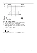
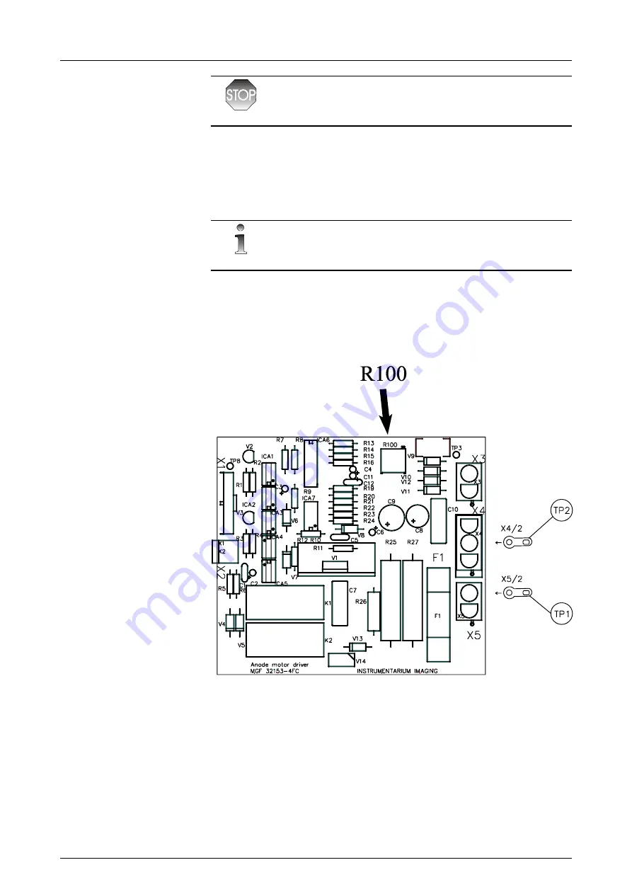
Immediately after pressing the exposure button, the testpoints TP1
and TP2 located at the edge of the AMD board (X4 pin 2 and X5 pin 2)
show voltage of 230V. With a
true RMS
(Digital Volt Meter) the
readout should be 30-42 VAC after 1.5 seconds (run voltage). It is
important also that the test #57 is completed without error.
NOTE!
Pay attention to potentiometer setting. It is different for 50 Hz and 60 Hz.
4
If necessary, adjust the anode running voltage with trimmer
potentiometer
R100
on AMD Board.
5
Exit the test #57 and also the service mode. Test the unit in normal
manual mode with maximum mAs value, repeat exposures for 5
times and verify that no error appears.
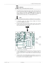
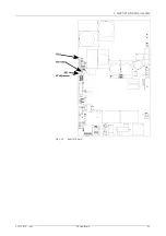
Fig 4.5.
Anode motor drive board (AMD)
6
During the exposure, listen that the first one of the power relays (K1)
on the INVERTER board is activated as the exposure button is
pressed, and that (K2) is activated after the preheat time, after app.
1.5 s.
7
Check also that on the INVERTER Board, the LEDs H2, H4, H5, H6, H7,
H11 and H12 and on the FILAMENT CONTROL board, the LEDs H2, H4,
H5, H6 and H7, turn on during the exposure.
Содержание Alpha RT 32551
Страница 1: ...GE Healthcare Alpha RT Installation Instructions 32551 IMG rev 6 0459 ...
Страница 2: ......
Страница 4: ......
Страница 42: ...3 Installation 36 GE Healthcare 32551 IMG rev 6 ...
Страница 51: ...4 Alpha RT softstart procedure 32551 IMG rev 6 GE Healthcare 45 Fig 4 10 Inverter board ...
Страница 52: ...4 Alpha RT softstart procedure 46 GE Healthcare 32551 IMG rev 6 ...
Страница 71: ...5 Setups alignments and adjustments 32551 IMG rev 6 GE Healthcare 65 Fig 5 2 Magnetic brake ...
Страница 94: ...5 Setups alignments and adjustments 88 GE Healthcare 32551 IMG rev 6 ...
Страница 96: ...6 Alpha RT installation step by step 90 GE Healthcare 32551 IMG rev 6 ...
Страница 97: ......
Страница 98: ......


