GEI-50299 Power Circuit Breakers Types AK-2 -15
and
AK-2/3-25
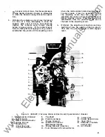
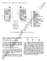
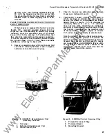
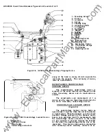
1.
Series Coil
2 .
Magnet
3.
Pallet
4 .
Pinion
5.
Escape Wheel
6.
D riving Segment
7.
S. T .D. Armature
8.
S. T .D. Calibration Spring
9.
Trip Arm
10.
Trip Paddle
1 1.
Trip Paddle Adjusting Screw
12.
L.T
.D .
Armature
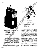
LEFT SIDE VIEW SHOWING
SHORT TIME DELAY MECHANISM
RIGHT SIDE VIEW SHOWING
LONG TIME DELAY MECHANISM
13.
L.T
.D.
Calibration Spring
14.
Instantaneous Trip Spring
FRONT VIEW SHOWING
MOUNTING BRACKET
(High Set)
1 5.
Spring Holder
1 6.
Calibration Clamp Nut
1 7.
Plunger
18.
Cylinder (Dashpot)
1 9.
Calibration Plate
20.
Clamping B racket
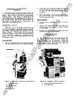
Figure 12. (695C189) E C - 1 Type Overcurrent Trip Device
NOTE :
Forcing the adjusting screw to either
extreme position may cause binding of the device
and should be avoided.
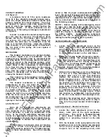
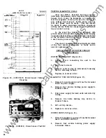
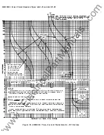
INSTANTANEOUS LOW-SET TRIPPING
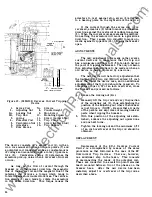
The low-set instantaneous pick-up point may
be varied by the adjustment knob (5), Figure 10.
The calibration in this case usually ranges from
BOo/a
to 2 50% of the series coil rating, the calibra
tion plate being indexed at values of 80%,
l OOo/0,
2 00% and 250% of the rating.
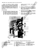
INS TANTANEOUS HIGH-SET TRIPPING
The high set instantaneous pick-up value may
have one of the following three ranges: 4 to 9
times coil rating;
6 to 12 times coil rating or
9 to 15 times coil rating. The pick-up setting
may be varied by turning the instantaneous trip
adjusting screw (4), Figure 1 1 .
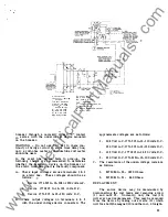
Three standard calibration marks will appear
on the operating arm at (9), Figure 1 1 , and the
value of these calibration marks will be indicated
22
by stampings on the arm as follows :
4X
6X
9X
6X
or
9X
12X
or
9X
1 2X
1 5X
At the factory, the pick-up point has been set
at the nameplate value of the instantaneous trip
current. (Usually expressed in times the ampere
rating of the trip coil.) The variation in pick-up
setting is accomplished by varying the tensile
force on the instantaneous spring. Turning the
adjustment screw changes the position of the
movable nut (2 ), Figure 1 1, on the screw. The
spring is anchored to this movable nut so that
when the position of the nut is changed, there is
a corresponding change in the spring load. As
the spring is tightened, the pick-up point is in
creased.
The top edge of the movable nut (2 ),
Figure 11 serves as an index pointer and should
be lined up with the center of the desired calibration
mark, punched slots on operating arm, to obtain
the proper instantaneous trip setting.
www
. ElectricalPartManuals
. com

